Sealing structure for sealing separator plates of fuel cell modules

a fuel cell and separator plate technology, applied in the direction of cell components, cell component details, electrochemical generators, etc., can solve the problems of insufficient quality, inability to meet, and precise control, and achieve the effect of reducing manufacturing costs, simplifying the manufacturing process of pemfc, and improving the quality of the whole fuel cell

Active Publication Date: 2005-06-16
ASIA PACIFIC FUEL CELL TECH
View PDF3 Cites 21 Cited by
  • Summary
  • Abstract
  • Description
  • Claims
  • Application Information

AI Technical Summary

Benefits of technology

[0016] The primary objective of this invention is to provide a single cell of a fuel cell, particularly a single cell of a PEMFC or a module thereof assembled by the single cells, by means of modulizing and unitizing the cell and module, to simplify the manufacturing process of a PEMFC. Because it is possible to test the performance of each single cell or module in advance according to this invention, the quality of the whole fuel cell is significantly improved and the manufacturing cost thereof is reduced to a mass production scale, thereby practically replacing the existing energy.

Problems solved by technology

However, although much effort has been put to settle the aforesaid problems, the result is not satisfied.
Generally speaking, there are two reasons adversely affecting the precise control: one is a failure to efficiently perform the leak and pollution proof functions between the anode and cathode bipolar plates, and the other is a failure to properly control the conductive compression pressure between each layer under an optimal status.
However, this construction for the fuel cell will result in the following problems: (1) The hydrogen supplied from the channels 101a of the anode plate 101 tends to leak out due to the gaps between the gasket 106 and the anode plate 101.
The leakage of hydrogen and oxygen significantly affects the electrochemical reactions of the fuel cell.
This disadvantageous phenomenon will be extremely obvious after a considerable duration of using the gaskets 106, 107.
Integral formation of those gaskets 106, 107 into a single gasket may improve the situation, but it cannot thoroughly solve the problem.
This is why the reaction gases often fail to diffuse uniformly, which is a severe block to the conductivity of a PEMFC.
Furthermore, because the whole PEMFC relies on the tie rods 110 disposed circumferentially to control its compression pressure, the pressure of the circumferential portion is significantly different from that of the central portion, which will adversely affect the operational effects of the fuel cell.
(3) Utilizing a gasket between the plates fails to efficiently isolate pollution and fails to properly locate each layer in position.
Further, because it is difficult to control in advance the compression pressure at an optimal range, it is not possible to pre-prepare a stock of the single cells in the modulized form to proceed with any of the possible types of tests for the purposes of cost reduction and mass production.
This is really the key factor of the failure to widely and effectively apply PEMFCs in the industry nowadays.

Method used


Image

  • Sealing structure for sealing separator plates of fuel cell modules
  • Sealing structure for sealing separator plates of fuel cell modules
  • Sealing structure for sealing separator plates of fuel cell modules

Examples


second embodiment

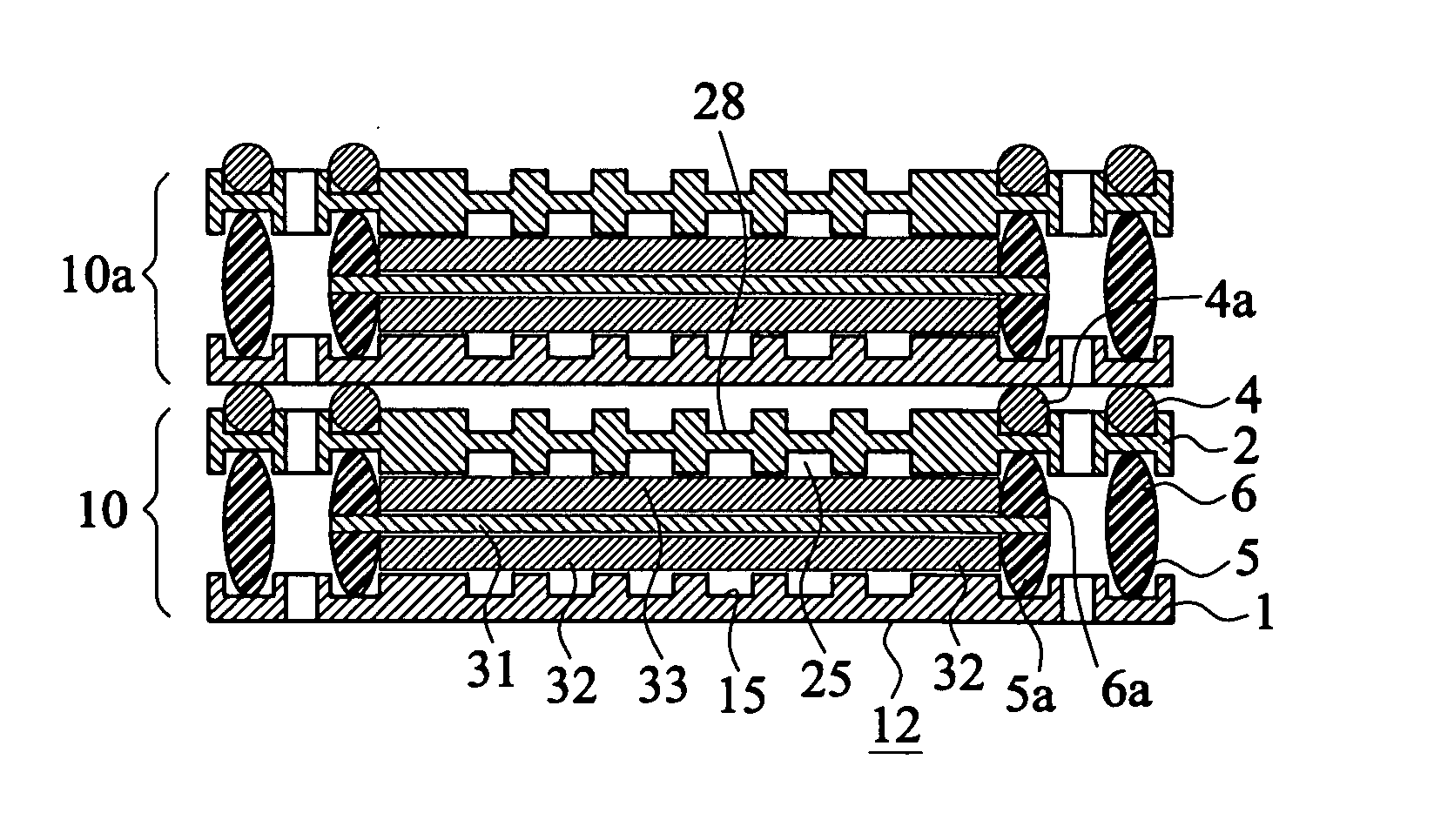
[0045]FIG. 6a shows a cross-sectional view of the present invention, in which two single cells are superimposed to form a fuel cell module. Two modulized single cells 10, 10a are formed in accordance with the technology as mentioned. Please refer to FIG. 6B. The single cells 10, 10a are then stacked together, such that the anode plate 1 at the bottom of the second single cell 10a is superimposed on the top of the cathode plate 2 of the first single cell 10. Accordingly, the plane structure of the second surface of the anode plate of the second single cell 10a forms the top surface of the coolant channels on the first surface 21 of the cathode plate 2, providing a passage for coolant flowing therethrough. By means of the silicon rubbers 4, 4a which are previously applied at the first surface 21 of the cathode plate 2 of the first single cell 10 and by compressing the two modulized single cells 10, 10a with a predetermined compression pressure, the two single cells 10, 10a are stably ...

third embodiment

[0046]FIG. 7A is a cross-sectional view showing the cell module constructed in accordance with the present invention. In the example shown, the cell module comprises two MEAs, one bipolar plate, an anode plate and a cathode plate. Similar reference numerals are used to identify elements that are similar or identical as that in FIGS. 5A to 5D.

[0047] In this embodiment, the cell module 10b comprises an anode plate 1, a bipolar plate 7 and a first MEA 3a. The anode plate 1 has a first surface 11, a second surface 12, a central portion 13, a circumferential portion 14, a plurality of anode gas channels 15, a peripheral groove 17, an extended groove 17a, and a plurality of ports. The bipolar plate 7 comprises a first surface 71, a second surface 72, a central portion 73, a peripheral portion 74, a plurality of cathode gas channels 75, a peripheral groove 77, an extended groove 77a, a peripheral groove 79, an extended groove 79a, and a plurality of ports. Furthermore, the first surface 71...

fourth embodiment

[0052]FIGS. 8A to 8B are cross-sectional views showing the stacking of two cell modules of FIG. 7D to form a fuel cell stack in accordance with the present invention. In assembly, two cell modules 10b, 10c manufactured by the technology are stacked together in series, such that the second surface of the anode plate of the cell module 10c is superimposed on the first surface of the cathode plate of cell module 10b, as shown in FIG. 8b. Accordingly, the flat structure of the second surface of the anode plate of cell module 10c forms the top surface of the coolant channels on the first surface of the cathode plate 8. By means of the silicon rubbers 91, 91a applied at the first surface of the cathode plate 8 of the cell module 10b, and by compressing the two cell modules 10b, 10c with a predetermined compression pressure, the two cell modules are bound together, forming a tight structure. Hence, the coolant channels are tightly sealed for flowing of coolant therethrough.


PUM

PropertyMeasurementUnit
temperatureaaaaaaaaaa
dielectric strengthaaaaaaaaaa

Abstract

A sealing structure for sealing a proton exchange membrane fuel cell is disclosed. The fuel cell includes a membrane electrode assembly, an anode plate, and a cathode plate. Both of the plates are formed with a peripheral groove and an extended groove at a circumferential portion thereof, and silicon rubber is applied to the peripheral groove and the extended groove. Before the silicon rubber is cured, the anode plate, the membrane electrode assembly and the cathode plate are stacked and compressed with a predetermined compression pressure, such that the silicon rubber at the peripheral groove of the anode plate binds correspondingly to the silicon rubber at the peripheral groove of the cathode plate to form a tight sealing at the circumferential portions between the anode plate and the cathode plate, and the membrane electrode assembly is tightly sandwiched between the silicon rubber at the extended groove of the anode plate and the silicon rubber at the extended groove of the cathode plate to form a tight sealing around the ports between the anode plate and cathode plate.

Description

BACKGROUND OF THE INVENTION [0001] 1. Field of the Invention [0002] The present invention relates to a proton exchange membrane fuel cell, particularly to a sealing structure for sealing single fuel cell and stacked fuel cell module. [0003] 2. Description of the Prior Art [0004] In the field of fuel cell technology, fuel cell is classified based on the electrolyte thereof. There are approximately five kinds of fuel cells which have been developed, namely, proton exchange membrane fuel cell or polymer electrolyte membrane fuel cell, abbreviated as PEMFC, alkaline fuel cell (AFC), phosphoric acid fuel cell (PAFC), molten carbonate fuel cell (MCFC) and solid oxide fuel cell (SOFC). Each kind of fuel cell has its own advantages, disadvantages and extent of applications. Among these known fuel cells, the PEMFC would be the most competitive power supply and has high practical value. [0005] Principally, a fuel cell is directed to use hydrogen and oxygen to proceed with electrochemical reac...

Claims


Application Information

Patent Timeline
Patent Type & Authority Applications(United States)
IPC IPC(8): H01M2/02H01M2/08H01M4/94H01M8/10H01M8/02H01M8/24
CPCH01M8/0258H01M8/0271Y02E60/50H01M8/241H01M8/248H01M8/0284H01M8/2483H01M8/0267H01M8/2457
Inventor YANG, JEFFERSON YS
Owner ASIA PACIFIC FUEL CELL TECH
Why Eureka
Try Eureka