
Method of Honing Bores

a technology of honing bores and honing holes, which is applied in the field of honing bore methods, can solve the problems of low efficiency, low efficiency, and high cost of engine block manufacture and assembly, and achieve the effect of improving the efficiency of honing process and reducing the cost of production and assembly

Inactive Publication Date: 2005-06-16
GEHRING GMBH & CO KG
View PDF2 Cites 15 Cited by
  • Summary
  • Abstract
  • Description
  • Claims
  • Application Information

AI Technical Summary

Benefits of technology

[0006] It is an object of the present invention to optimize honing of bores that have a hardened section. It is therefore the object of the present invention to further develop a method for honing bores, in particular, cylinder bores in crankcases of internal combustion engines, such that honing is more efficient and performed with greater dimensional precision.
[0008] According to an advantageous embodiment of the method, the adjustment of the working stroke of the honing tool can be carried out toward the adjoining section of reduced hardness of the bore. By this measure, a gradual transition between the honed and the unhoned section is achieved, i.e., between the soft section and the hardened section of the bore. In another embodiment of the method according to the invention, the adjustment of the working stroke of the honing tool is carried out in the direction toward the open end of the hardened section. In this way, a slight alteration of the bore opening can result or a burr that is present can be removed.
[0009] Inasmuch as a particularly smooth transition from the hardened section to the softer section is to be achieved and additionally the bore opening is to be machined, it is advantageous to carry out the adjustment of the working stroke of the honing tool in the direction of the adjoining section of the bore as well as in the direction of the open end of the hardened section.
[0010] In the case of certain bores, it can be advantageous that the end of the bore has a counterbore so that the honing process in this area can be designed accordingly. The term counterbore is used in fine machining to define an outwardly widening contour near the end of a bore. In this connection, the shape of the bore deviates from the ideal shape of a cylinder. This means an increase of the bore diameter at the respective end of the bore. The counterbore produced accordingly relieves the subsequent honing operation in that at the upper end of the bore less material must be removed.
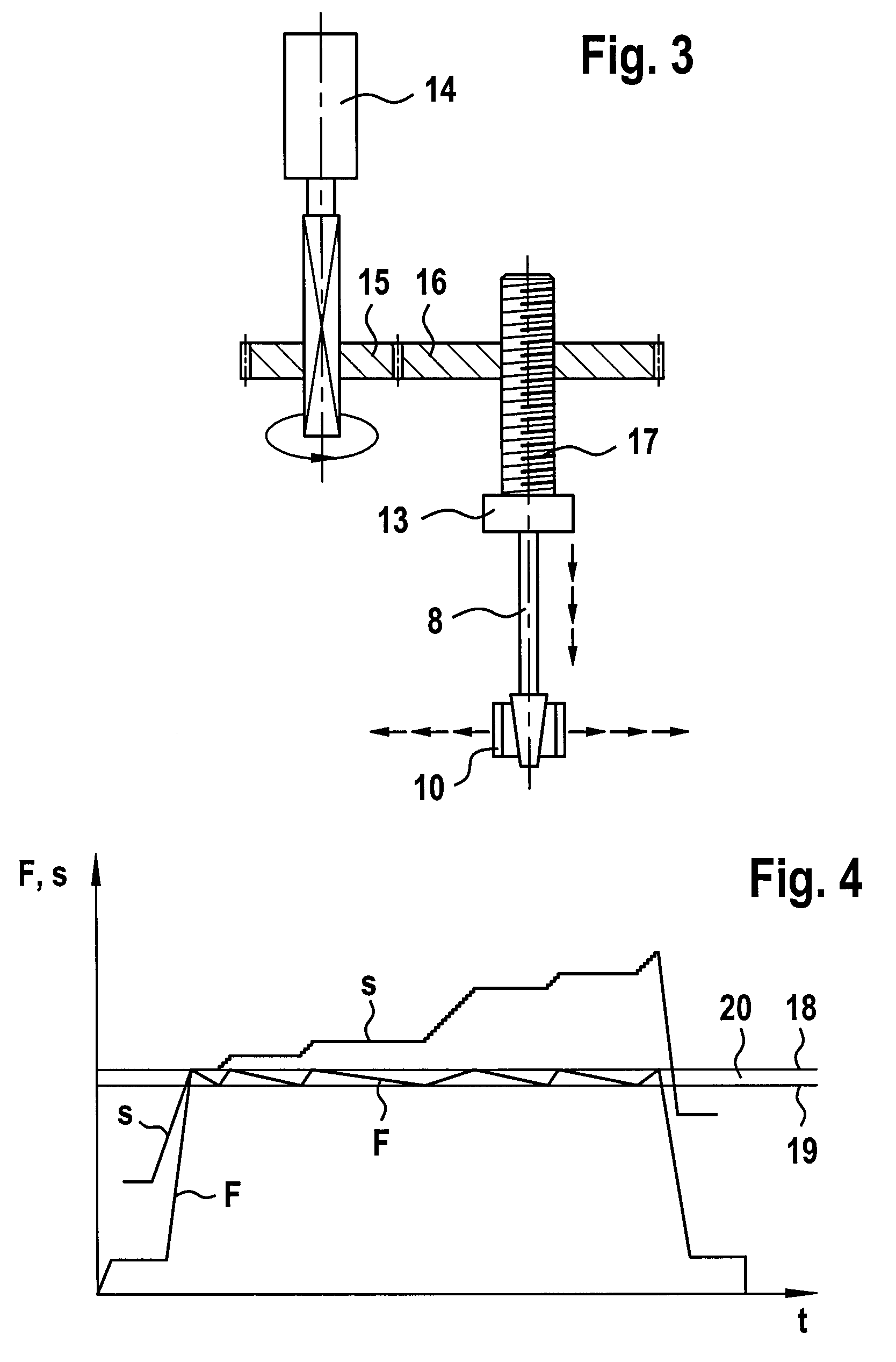
[0012] Moreover, it is advantageous to measure the advancing (feeding) force of the honing stones continuously and to maintain the advancing force within a pre-determined bandwidth of an upper limit and a lower limit and to perform the expansion of the honing stones in steps when reaching the lower limit of the advancing force, respectively. In this way, during the entire honing operation the advancing force is maintained constant within narrow limits so that undesirably high pressing forces of the honing stones on the bore wall can be prevented.

Problems solved by technology

Such cylinder liners however result in relatively high costs with regard to manufacture as well as assembly of the engine block.
When using induction hardening, non-concentric bore constrictions result; this prevents the use of conventional honing processes.

Method used


Image

  • Method of Honing Bores
  • Method of Honing Bores
  • Method of Honing Bores

Examples


Embodiment Construction

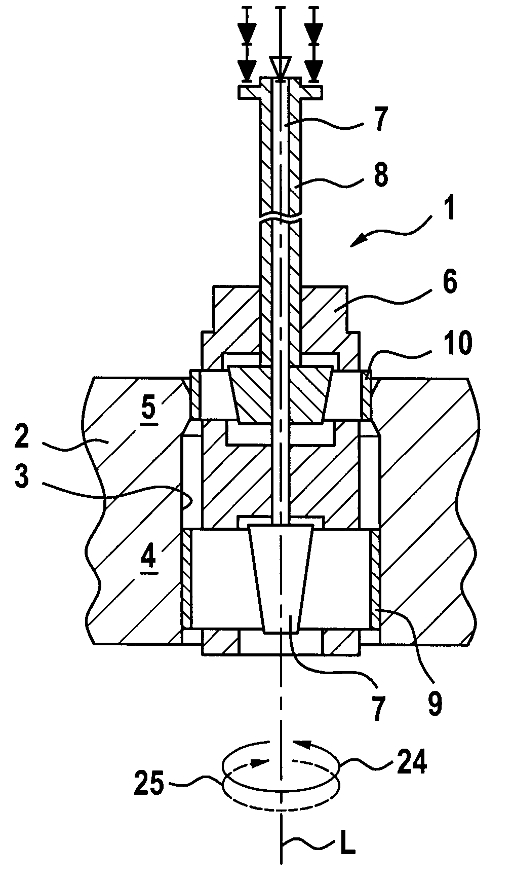
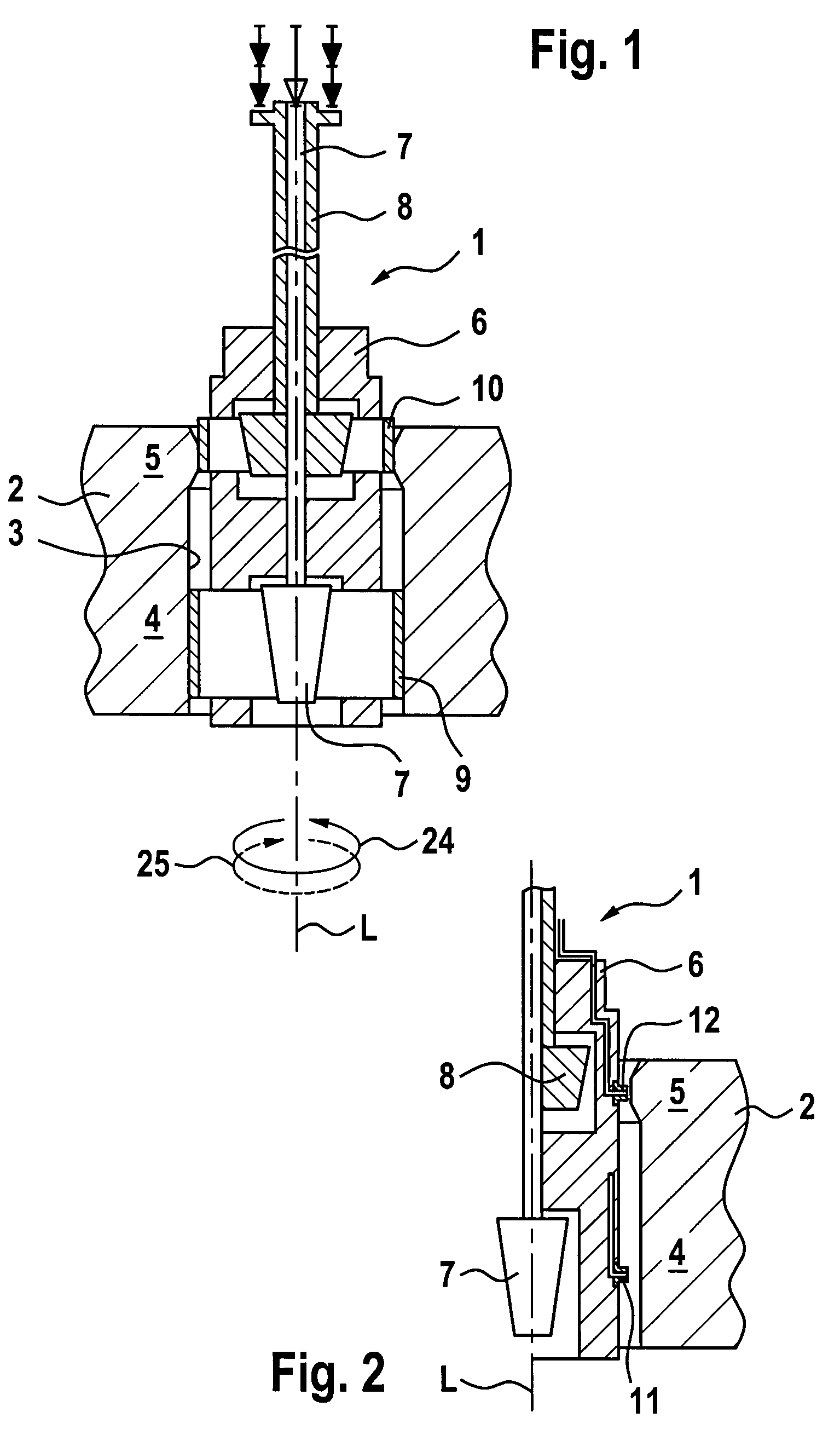
[0019]FIG. 1 shows a longitudinal section of a honing tool 1 which is suitable for coaxial honing. The honing tool 1 is positioned in a bore 3 of a workpiece 2 wherein the workpiece 2, for example, is the crank case of an internal combustion engine. The bore 3 comprises a section 4 that is not hardened and a hardened section 5, wherein the hardened section 5 is provided at the upper end of the bore 3, as shown in FIG. 1. The hardened section 5 can be produced by induction hardening, for example. The honing tool 1 comprises a tool head 6 with radially expandable honing stones 10 and radially expandable guides 9. The guides 9 are supported on the bore wall within the section 4 that is not hardened, while the honing stones 10 rest against the wall in the hardened section at a predetermined force load. A first advancing device 7 for the guides 9 and a second advancing device 8 for the honing stones 10 are provided. The second advancing device 8 is a force-guided electro-mechanical step ...


PUM

PropertyMeasurementUnit
hardnessaaaaaaaaaa
thicknessaaaaaaaaaa
forceaaaaaaaaaa

Abstract

In a method for honing a bore having first and second sections sequentially arranged in an axial direction of the bore, wherein the first section is hardened so that the first and second sections have different hardness, a honing tool is radially supported by positioning guides of the honing tool on the second bore section first section is machined with honing stones arranged on the honing tool to remove material from the first section. During machining of the first section, the honing tool is expanded by feeding the honing stones according to a defined feeding mode against a surface of the first section by a force-guided electro-mechanical advancement. During machining of the first section, the working stroke of the honing tool is adjusted continuously at least toward the end of the honing process. Feeding of the guides is realized independently of feeding of the honing stones.

Description

BACKGROUND OF INVENTION [0001] 1. Field of the Invention [0002] The invention relates to a method of honing bores, in particular, cylinder bores in crankcases of internal combustion engines. [0003] 2. Description of the Related Art [0004] In truck engines, cylinder linings that are made by spin casting are often employed as piston bearing surfaces because this material is more wear resistant than the material of the engine block. Such cylinder liners however result in relatively high costs with regard to manufacture as well as assembly of the engine block. Therefore, it has already been proposed to partially harden the piston bearing surface of the engine block within the upper reversing area of the piston movement in order to achieve in this way a higher wear resistance. In this way, a separate cylinder liner is not needed. For example, hardening can be achieved by using a method employing a laser; however, the more economical and cost efficient alternative is induction hardening. ...

Claims


Application Information

Patent Timeline
Patent Type & Authority Applications(United States)
IPC IPC(8): B24B33/02B24B33/08
CPCB24B33/083B24B33/02
Inventor KLINK, ULRICHWIEDERHOLD, JOACHIMWOLF, JURGEN
Owner GEHRING GMBH & CO KG
Learn More