Powder feeder for material deposition systems

a technology of material deposition system and feeder, which is applied in the direction of packaging, manufacturing environment conditioning, liquid/fluent solid measurement, etc., can solve the problems of very inaccurate process, limited choice of materials, and the potential for making very complex parts of solid, hollow or lattice construction, etc., to achieve accurate dimensions, enhance mechanical properties of parts, and eliminate substrate warping

Inactive Publication Date: 2005-06-23
OPTOMEC DESIGN CO
View PDF43 Cites 156 Cited by
  • Summary
  • Abstract
  • Description
  • Claims
  • Application Information

AI Technical Summary

Benefits of technology

[0025] Heating the substrate and the deposition produces parts with accurate dimensions by eliminating warping of the substrate and deposition. A prescribed temperature profile is used for processing tempered material. A temperature profile for heat treating may be used to enhance the mechanical properties of the part by ensuring the correct material microstructure during processing.
[0026] Although the prior use of DMD processes has produced soli

Problems solved by technology

The process then was very inaccurate, and the choice of materials was limited.
Moreover, there is a potential for making very complex parts of either solid, hollow or latticed construction.
Such a deposition process would seem to have substantial problems of warping and distorting the deposited layers because of incomplete melting of feedstock material.
The methods described are very specific to cermets and do not employ solid models and automated processes.
It is not a direct fabrication method for three-dimensional objects with graded or multiple material structures.
The method does not create structures of gradient material.
The patent describes the advantages

Method used


Image

  • Powder feeder for material deposition systems
  • Powder feeder for material deposition systems
  • Powder feeder for material deposition systems

Examples


Embodiment Construction

[0096] 1. Forming Structures Directly from a CAD Solid Model

[0097] The present invention comprises apparatus and methods for fabricating metallic hardware with exceptional material properties and good dimensional repeatability. The term “net shape” refers to an article fabricated to the approximate desired size and features, solid or latticed, by a process which requires little or no machining. The prior art in this technology has focused on methods to enable the deposition process. However, little work has been done on how to best control the process to achieve a desired outcome in a solid structure.

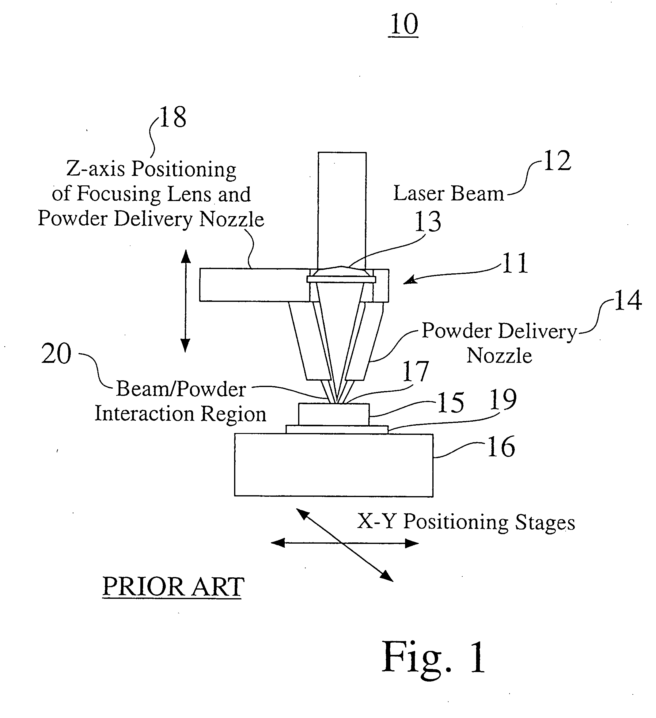
[0098] The present invention uses the laser-based process to provide users with the ability to create a net shape or near-net shape, fully dense, metallic object directly from a computer aided design (CAD) solid model. The shapes are created a layer at time. In this Specification and in the claims that follow, the invention is referred to as a directed material deposition (DMD) proces...


PUM

PropertyMeasurementUnit
Fractionaaaaaaaaaa
Pressureaaaaaaaaaa
Compositionaaaaaaaaaa

Abstract

A method and apparatus for embedding features and controlling material composition in a three-dimensional structure (130) is disclosed. The invention enables the control of material characteristics, within a structure (130) made from a plurality of materials, directly from computer renderings of solid models of the components. The method uses stereolithography and solid model computer file formats to control a multi-axis head (480) in a directed material deposition process (123). Material feedstock (126, 127) is deposited onto a pre-heated substrate (19). Depositions (15) in a layer-by-layer pattern, defined by solid models (141, 146), create a three-dimensional article having complex geometric details. Thermal management of finished solid articles (250-302), not available through conventional processing techniques, is enabled by embedded voids (152) and/or composite materials (126, 127), which include dissimilar metals (210, 216). Finished articles control pressure drop and produce uniform coolant flow and pressure characteristics. High-efficiency heat transfer is engineered within a solid structure by incorporating other solid materials with diverse indexes. Embedding multi-material structures (132, 134) within a normally solid component (141) produces articles with diverse mechanical properties. Laser and powder delivery systems (420, 170) are integrated in a multi-axis deposition head (480) having a focused particle beam (502) to reduce material waste.

Description

CROSS-REFERENCES TO RELATED PATENT APPLICATIONS & CLAIMS FOR PRIORITY [0001] This application is a continuation application of U.S. patent application Ser. No. 10 / 128,658, entitled “Forming Structures from CAD Solid Models”, filed on Apr. 22, 2002, which is a continuation-in-part application of U.S. patent application Ser. No. 09 / 568,207, now U.S. Pat. No. 6,391,251, entitled Forming Structures from CAD Solid Models, filed on May 9, 2000, which claims the benefit of the filing of U.S. Provisional Patent Application Ser. No. 60 / 143,142, entitled “Manufacturable Geometries for Thermal Management of Complex Three-Dimensional Shapes”, filed on Jul. 7, 1999. The specifications and claims of all of the above references are hereby incorporated herein by reference.FIELD OF THE INVENTION [0002] The present invention relates to the field of direct material deposition processes which allow complex structures to be fabricated efficiently in small lots to meet stringent requirements of a rapidly...

Claims


Application Information

Patent Timeline
IPC IPC(8): B05B7/14B22F3/105B23K26/34B29C33/02B29C33/04B29C33/38B29C41/20B29C45/73B29C67/00F28F7/02
CPCB05B7/14B23K26/322B23K26/34B29C33/02B29C33/046B29C33/3842B29C41/20B29C45/7312B29C67/0051B29C67/0077B29C67/0092B29C70/68F28F7/02B22F2003/1057B23K26/3206B23K26/3213B22F3/1055B23K26/32B29C64/153B29C64/40B22F2999/00B23K2103/04B23K2103/05B23K2103/12B23K2103/14B23K2103/26B23K2103/50B33Y10/00B29C64/371Y02P10/25B22F12/30B22F12/48B22F10/385B22F10/80B22F12/52B22F10/31B22F10/25B22F12/53B22F2203/11B22F2203/03
Inventor DULLEA, KEVIN J.SMITH, MARK E.KEICHER, DAVID M.
Owner OPTOMEC DESIGN CO
Why Eureka
Try Eureka