Flow-through assay devices

a flow-through assay and electrode technology, applied in the field of analytical procedures and devices, can solve the problems of large sample volume, insufficient contact of the sample with the working electrode surface, and the flow-through electrochemical biosensors that are described above, and achieve the effect of facilitating the flow of the test sampl

Inactive Publication Date: 2005-06-23
KIMBERLY-CLARK WORLDWIDE INC
View PDF30 Cites 87 Cited by
  • Summary
  • Abstract
  • Description
  • Claims
  • Application Information

AI Technical Summary

Benefits of technology

[0018] In accordance with still another embodiment of the present invention, a flow-through assay device is disclosed for detecting the presence or quantity of an analyte residing in a test sample. The flow-through assay device comprises a fluidic microchannel printed onto a substrate that facilitates the flow of the test sample to a detection working electrode. The microchannel has a characteristic dimension of from about 0.5 to about 500 micrometers. A specific binding capture ligand for the analyte is applied to the detection working electrode. The detection working electrode is capable of generating a measurable detection current, wherein the amount of the analyte within the test sample is proportional to the detection current generated at the detection working electrode.

Problems solved by technology

Unfortunately, conventional flow-through electrochemical biosensors, such as described above, possess various problems.
For instance, traditional flow-through assay devices require a large sample volume because of the presence of a large sampling pad, wicking pad, and porous membrane.
Moreover, the contact of the sample with the working electrode surface is not always sufficient because a large portion of the sample does not flow through the electrode surface, rather it flows through the membrane itself and bypasses the working electrode.
In addition, other than the membrane, there are no flow control mechanisms.
On the other hand, if a fast moving membrane (e.g., nylon mesh) is used, the flow speed may be too fast to handle the data acquisition or necessary reaction time.

Method used


Image

  • Flow-through assay devices
  • Flow-through assay devices
  • Flow-through assay devices

Examples


example 1

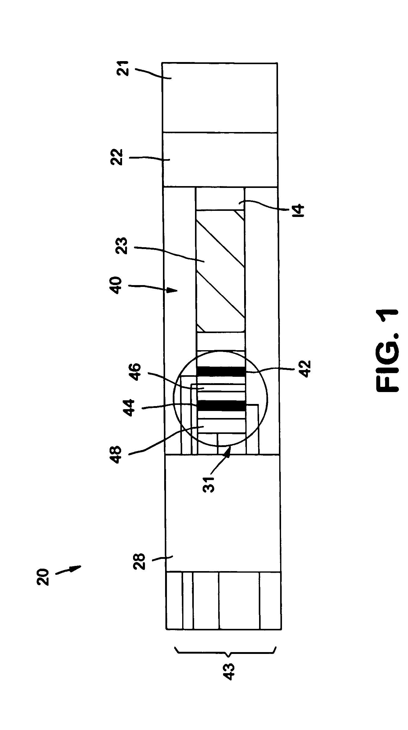
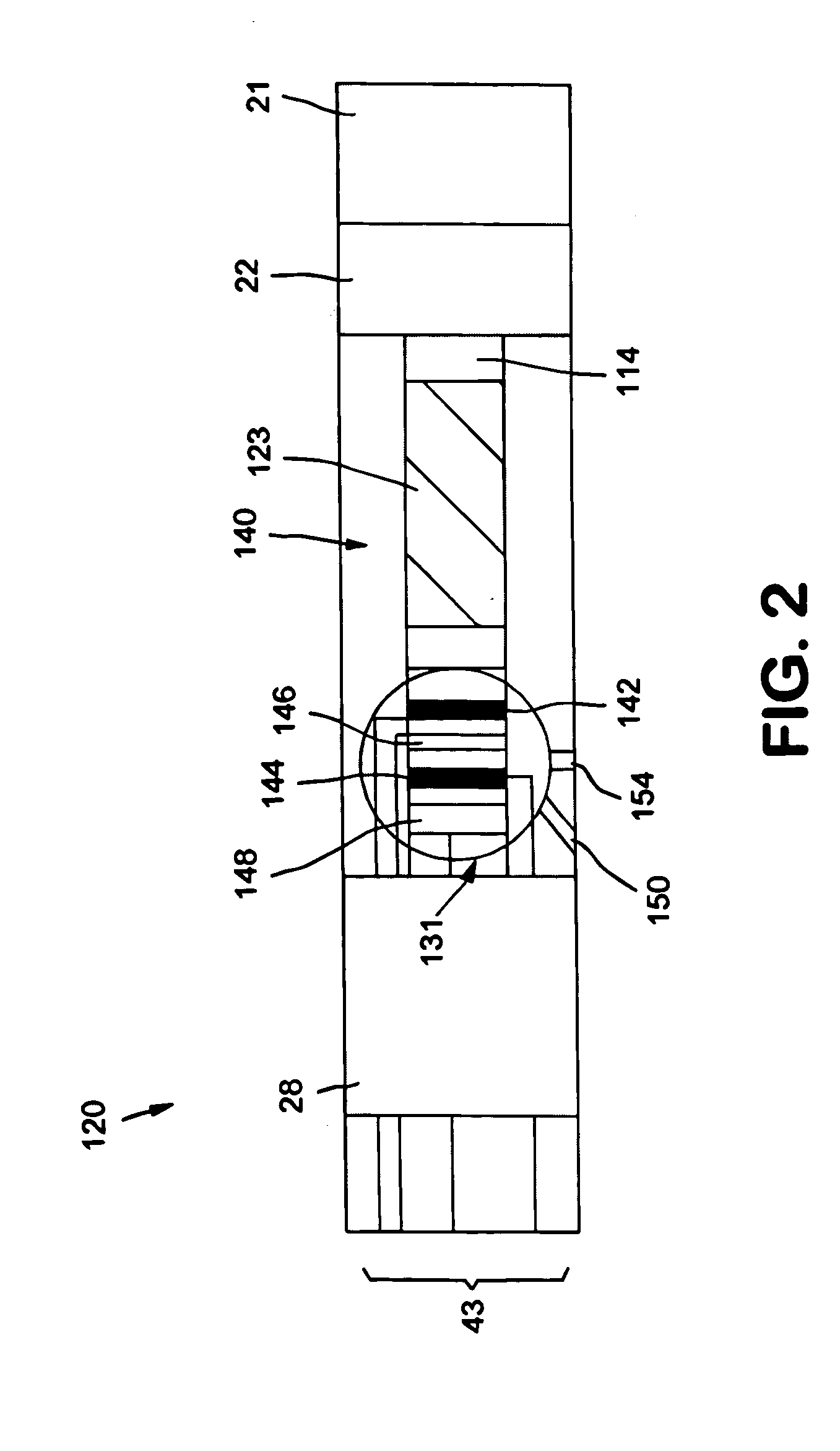
[0074] Electrodes were printed onto Mylar® substrates obtained from DuPont. The substrates had a length of 0.5 centimeters and a width of 1.5 centimeters. Carbon (7101 or 7102), silver (5000), and silver / silver chloride (5847) inks were obtained from DuPont Biosensor Group of Research Triangle Park, North Carolina. For printing the inks, a screen frame was first fixed onto a screen frame holder and adjusted. Initially, a silver ink line was printed on the substrate to enhance the conductivity between the printed leads and electrodes. Thereafter, carbon ink was printed over the silver ink line to form a detection working electrode, calibration working electrode, and counter electrode. The silver / silver chloride ink was printed onto the substrate to form a reference electrode. Leads for the electrodes were also printed. The resulting electrode strips were left at room temperature for 2 hours, and then heated at 37° C. for 2 hours. The temperature was then raised to 60° C. and dried an...

example 2

[0075] The ability to print flow channels onto the electrode strip of Example 1 was demonstrated. Specifically, an insulation layer and flow channel were then printed simultaneously onto the substrates using a UV-curable dielectric composition available from DuPont under the name “5018G.” Printing was performed with a screen printer available from Affiliated Manufacturers, Inc. (“AMI-Presco”) of North Branch, N.J. under the name “HC-53.” The screen frame utilized had a size of 5×7 inches, a mesh size of 80×0.0037 to 400×0.0007, and a stencil angle of 22 to 45 degrees. The insulation layer essentially covered the substrate area not otherwise covered by the electrodes, leads, or flow channels. The resulting flow channel had a length of 2.5 centimeters and a width of 0.5 centimeters. The height of the flow channel ranged from about 10 to about 150 micrometers, and was measured using a micrometer available from Mitutoyo America Corporation of Aurora, Ill. The insulation layer and channe...

example 3

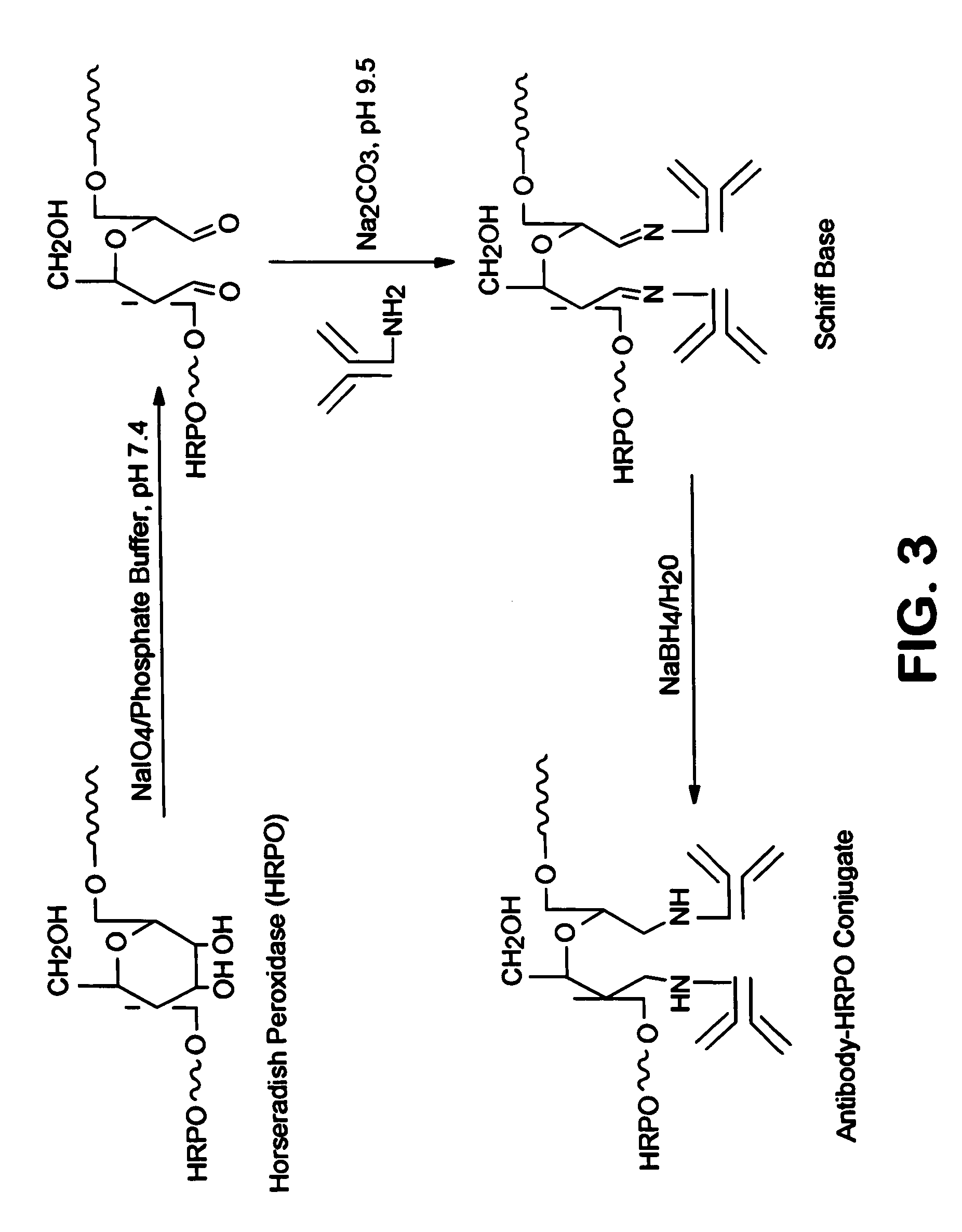
[0076] Membrane strips of a nylon mesh membrane (30 mesh size, commercially available from Millipore Corp. of Billerica, Mass.) were provided that had a width of 4.5 centimeters and a length of 15 centimeters. To the bottoms of the strips, two glass fiber pads (sample and conjugate pads) were attached using tape. The conjugate pad was in direct contact with the membrane, and the sample pad was in direct contact with the conjugate pad. The conjugate pad was treated with 3 microliters of LH-α-HRP monoclonal antibody conjugate (5 micrograms per milliliter in PBS buffer) and dried for 30 minutes. The LH-α-HRP monoclonal antibody conjugate was obtained from Fitzgerald Industries Int'l of Concord, Mass. The membrane strips were placed onto a sampling instrument commercially available from Kinematic Automation of Twain Harte, Calif. under the name “Matrix 2210 (Universal Laminator).” Thereafter, the strips were cut into individual strips having a width ranging from 1 to 10 millimeters usin...


PUM

PropertyMeasurementUnit
heightaaaaaaaaaa
heightaaaaaaaaaa
heightaaaaaaaaaa

Abstract

A flow-through assay device capable of detecting the presence or quantity of an analyte of interest is provided that is accurate, reliable, and easy-to-use. The device contains a substrate printed with a channel to facilitate the flow of a test sample to a detection working electrode. The detection working electrode communicates with affinity reagents, such as redox mediators and capture ligands. For instance, capture ligands that are specific binding members for the analyte of interest are applied to the detection electrode to serve as the primary location for detection of the analyte.

Description

BACKGROUND OF THE INVENTION [0001] Various analytical procedures and devices are commonly employed in assays to determine the presence and / or absence of analytes in a test sample. For instance, immunoassays utilize mechanisms of the immune systems, wherein antibodies are produced in response to the presence of antigens that are pathogenic or foreign to the organisms. These antibodies and antigens, i.e., immunoreactants, are capable of binding with one another, thereby causing a highly specific reaction mechanism that may be used to determine the presence or concentration of that particular antigen in a biological sample. There are several well-known techniques for detecting the presence of an analyte. [0002] One such technique is described in WO 01 / 38873 to Zhang, Zhanq describes flow-through electrochemical biosensors designed to detect the presence of an analyte. FIG. 2 of Zhang, for instance, illustrates a sensor assembly 5 that includes an absorbent pad 18, a wicking mesh 22, an...

Claims


Application Information

Patent Timeline
Patent Type & Authority Applications(United States)
IPC IPC(8): G01N33/52G01N33/543G01N33/558
CPCG01N33/52G01N33/558G01N33/5438
Inventor YANG, KAIYUANBOGA, RAMESHBABUFEASTER, SHAWN RAYKAYLOR, ROSANN MARIE MATTHEWSCOHEN, DAVID SAMUEL
Owner KIMBERLY-CLARK WORLDWIDE INC
Why Eureka
Try Eureka