Method and apparatus for chemical synthesis

a chemical synthesis and apparatus technology, applied in the field of large scale, can solve the problems of limited yield, large quantity of monosilane, low yield of higher-order silanes, etc., and achieve the effect of facilitating continuous operation

Inactive Publication Date: 2005-06-30
ASM AMERICA INC
View PDF9 Cites 26 Cited by
  • Summary
  • Abstract
  • Description
  • Claims
  • Application Information

AI Technical Summary

Problems solved by technology

The majority of these synthetic methods suffer from numerous problems that will have to be solved before cost-effective, safe commercial synthesis of these valuable compounds can be achieved.
The use of aqueous acid solutions results in limited yields due to hydrolysis of the products as they are formed.
This results in the production of large quantities of monosilane and low yields of higher order silanes.
Liquid ammonia syntheses of this nature are more effective due to elimination of these hydrolysis reactions, but commercial-scale synthetic reactions are difficult to implement.
The use of hydrogen sulfide or a metal sulfide as a catalyst is problematic from safety and final product purity considerations.
That is, hydrogen sulfide is a highly toxic, high-pressure gas and it is difficult to separate it from higher order silane compounds.
Reduction reactions of higher order chlorosilanes, SinCl2n+2, are highly effective on a laboratory scale, but the starting chlorine compounds are difficult to synthesize and expensive.
These reactions typically involve the combination of highly flammable ether solvents and flammable hydridic reducing agents and can be difficult to control when synthesizing on larger scales.
Furthermore, the reactions can be very dangerous from the perspective of fire hazards and the separation of the desired silane compound(s) from the solvent and byproducts can be difficult.
The combination of chemicals required presents a severe fire hazard during synthesis, particularly on a commercial scale.
Reaction of partially halogenated higher order silanes and alkali metal silyl salts requires costly synthetic intermediates and involves the use of highly reactive chemicals in ether solvents.
As a result, this method presents serious fire hazard issues.
Prior art electric discharge methods that rely upon the use of monosilane and reduced pressure processes are expensive and typically result in low yields of higher order silanes, SinH2n+2 (n>2), with a large percentage of the starting materials being converted to amorphous hydrogenated silicon particles.
This method precludes use of pure polysilanes or polygermanes, particularly liquids (i.e., SinH2n+2 where n≧3 and GenH2n+2 where n≧2), in deposition reactions and further limits the application of the mixtures obtained to atmospheric pressure.
The apparatus employed does not allow isolation, purification and collection of the higher order polysilanes and polygermanes.
In the catalytic methods of the prior art, the catalytic activity of the platinum-group and Lanthanide compounds is typically low, the reactions require extended periods of time and the yield of the desired higher order silanes is typically low.
Furthermore, the cost of the starting materials of these reactions is typically high and contamination of the final products with unwanted metal impurities can be a serious issue.
Traditional distillation techniques require heating of the mixture, resulting in the thermal decomposition of higher order silanes during the distillation.
Furthermore, the method requires multiple, lengthy reaction steps, is not overly efficient and requires a complex apparatus.
As a result, the commercial maturity of this technique is not sufficient to provide large quantities of pure, higher order silanes.
The lack of an efficient, safe and cost effective method for synthesizing, isolating and purifying higher order polysilanes and polygermanes, with a high degree of purity and on an industrial scale, hinders their use in semiconductor processes.

Method used


Image

  • Method and apparatus for chemical synthesis
  • Method and apparatus for chemical synthesis
  • Method and apparatus for chemical synthesis

Examples


example

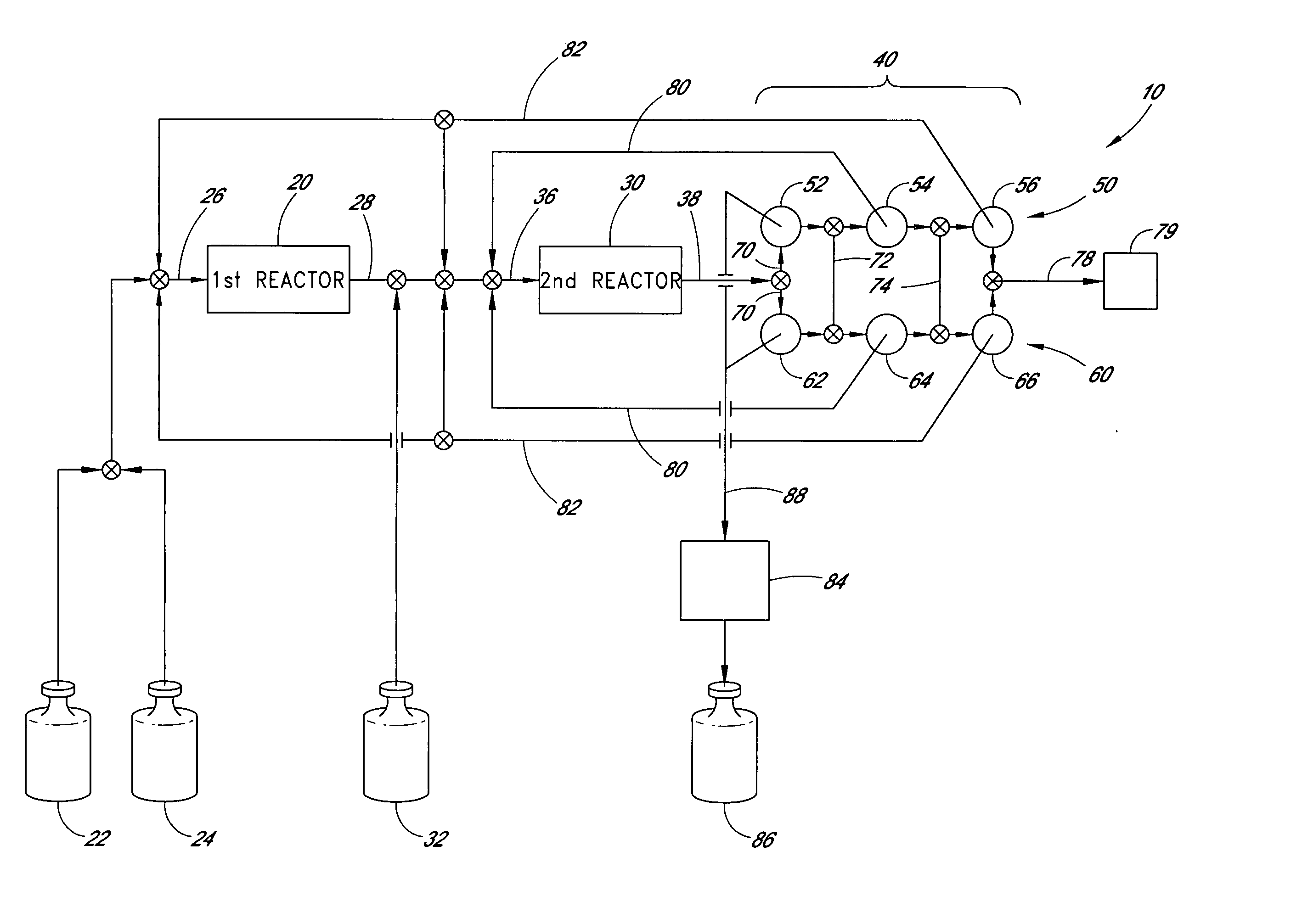
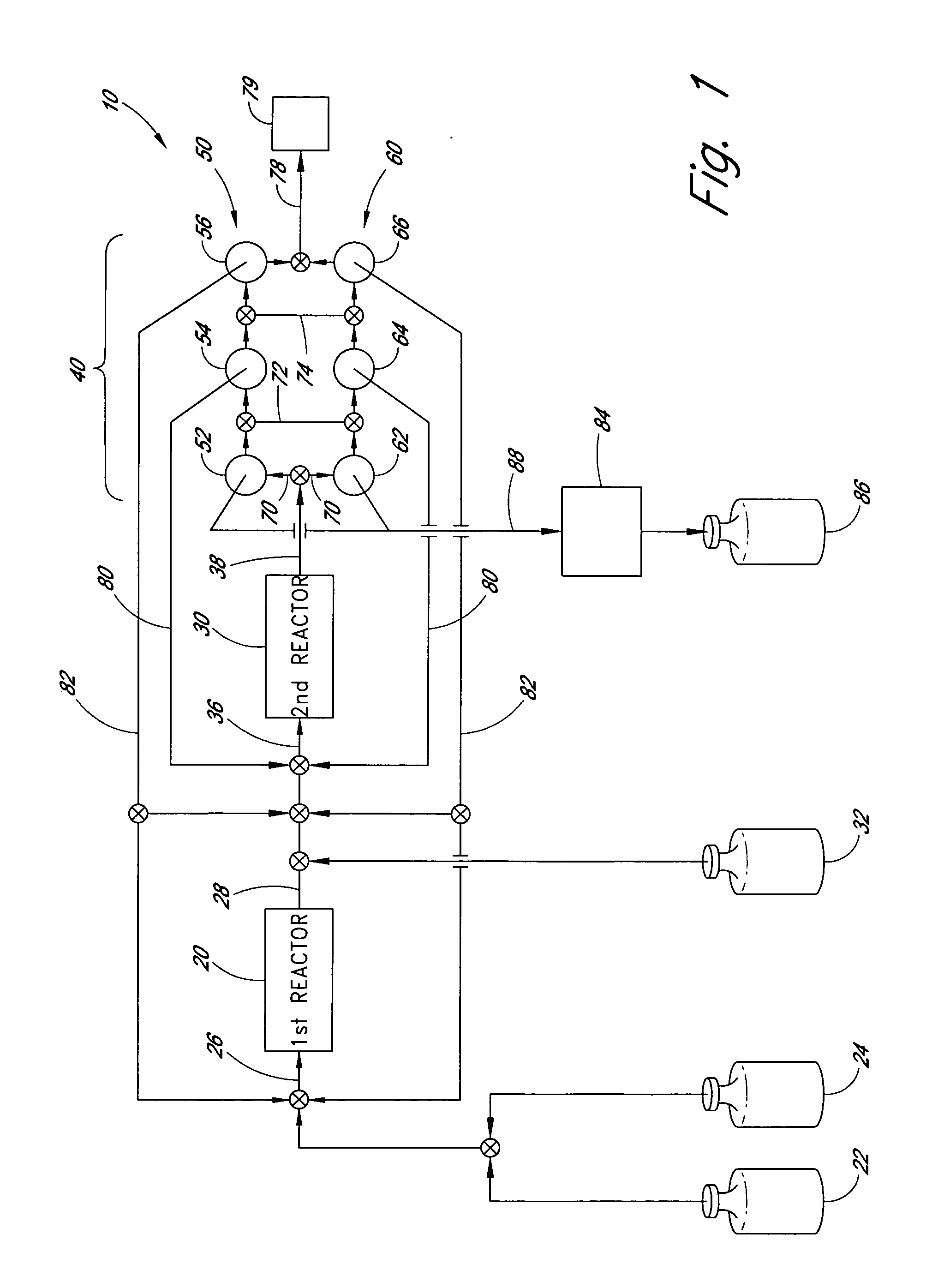
[0054] An exemplary apparatus and process is provided below for the production of trisilane from monosilane.

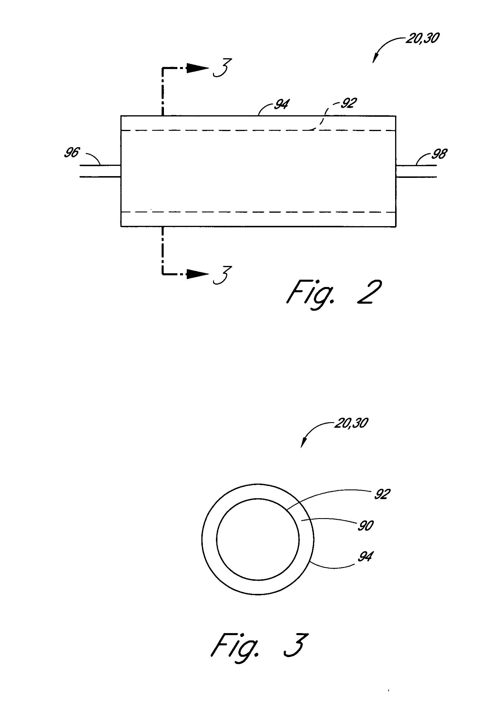
[0055] First Reactor: A 5 cm long concentric stainless steel tube with inner and outer walls separated by evacuated space, inner wall is grounded, serving as the outer electrode for the reactor. The evacuated space between the inner and outer stainless steel walls serves as thermal insulation. Within the inner stainless steel wall is another cylindrical element comprising alumina (or other suitable dielectric material) coated with a low work function metal (e.g., silver, tungsten, etc. . . . ), connected to high frequency electric source via contact and conductor, also 5 cm in length. The inner stainless steel wall and the concentric metal-coated alumina cylinder (i.e., the electrodes) are spaced about 0.1 cm apart, defining the reaction space therebetween. A conduit is provided for feeding reactants to the volume present between the two electrodes and a conduit is provided f...


PUM

PropertyMeasurementUnit
diameteraaaaaaaaaa
diameteraaaaaaaaaa
diameteraaaaaaaaaa

Abstract

An apparatus is provided for synthesis and collection of higher order chemical compounds from lower order precursors. The apparatus includes a first silent electric discharge reactor configured to synthesize an intermediate product (e.g., disilane) from a precursor chemical (e.g., monosilane). A second silent electric discharge reactor is connected downstream of the first reactor. This second reactor is configured to convert the intermediate product into the higher order chemical compound (e.g., trisilane). Multiple condensation traps are also connected to receive effluent from the second reactor, which will generally include the compound of interest as well as unreacted precursor and intermediate product. In the illustrated embodiment, a parallel second condensation traps is also included to shunt flow and continue collection while the chemical of interest is removed for purification. Moreover, parallel second condensation traps for the intermediate product and unreacted (or recombined) precursor allow continued collection while the contents of the first traps are recycled in the reactor(s).

Description

REFERENCE TO RELATED APPLICATION [0001] This application is a divisional of U.S. patent application Ser. No. 10 / 197,899 filed Jul. 16, 2002, which claims the priority benefit under 35 U.S.C. §119(e) to U.S. provisional patent application No. 60 / 306,534, filed Jul. 19, 2001 of Michael A. Todd, entitled METHOD AND APPARATUS FOR CHEMICAL SYNTHESIS, both of which are hereby incorporated by reference in their entireties.FIELD OF THE INVENTION [0002] The invention relates to the field of large scale, commercial volume synthetic chemistry. It relates more specifically to the synthesis of trisilane, Si3H8, as well as to other higher order silicon hydrides (SinH2n+2), related higher order silane chemical derivatives and polygermanes (GenH2n+2). Trisilane and other higher order silane chemical derivatives are likely to be useful as chemical precursors for film deposition within the semiconductor industry. BACKGROUND OF THE INVENTION [0003] The synthesis of higher order silanes, SinH2n+2 (wher...

Claims


Application Information

Patent Timeline
Patent Type & Authority Applications(United States)
IPC IPC(8): B01J19/08C01B33/04
CPCB01J19/088B01J2219/00191B01J2219/0286C01B33/04B01J2219/083B01J2219/0849B01J2219/0879B01J2219/0809
Inventor TODD, MICHAEL A.
Owner ASM AMERICA INC
Why Eureka
Try Eureka