Direct antifreeze cooled fuel cell power plant with passive water management

Inactive Publication Date: 2005-06-30
INT FUEL CELLS
View PDF9 Cites 9 Cited by
  • Summary
  • Abstract
  • Description
  • Claims
  • Application Information

AI Technical Summary

Benefits of technology

[0011] The power plant also includes a pressure control system for maintaining a positive pressure differential between the fuel stream passing through the fuel channels of the porous anode cooler plate and the direct antifreeze passing through the coolant channels of the anode cooler plate. The positive pressure differential facilitates movement of any condensed water from the fuel reactant stream into the coolant channels and into the direct antifreeze solution, and restricts movement of the direct antifreeze from the porous anode cooler plate into the anode support layers and anode catalyst. The pressure control system may also maintain a positive pressure differential between the oxidant stream passing through the oxidant channels of the cathode water management plate and the product water passing through the pores and water management channels of the water management plate in order to facilitate movement of fuel cell product water and any condensed water within the oxidant stream away from the cathode support layers and cathode catalyst and into the cathode water management plate to avoid flooding of the cathode catalyst and to remove excess fuel cell product water out of the fuel cell.
[0013] In a preferred embodiment, the fuel cell power plant includes a coolant loop that directs flow of the direct antifreeze solution from the coolant channels of the porous anode cooler plate through a coolant pump, an evaporator and a radiator and back to the cooler plate to control a concentration of and cool the direct antifreeze solution. An oxidant recycle line may also direct a portion of heated oxidant from the oxidant discharge line into the evaporator to facilitate evaporation of any water from the direct antifreeze solution. In varying embodiments, the pressure control system may consist of restriction valves on anode and cathode exhausts combined with a pressurized reducing fluid source and an oxidant blower to elevate the pressure of the reactant streams within the fuel cell. Additionally, a pressure control valve may be utilized on a coolant feed line to reduce pressure of the direct antifreeze solution within the fuel cell.
[0016] It is yet another purpose to provide a direct antifreeze cooled fuel cell power plant with passive water management that restricts liquid contact between the direct antifreeze solution and cathode catalysts of fuel cells of the plant.

Problems solved by technology

Because the fuel cell product water is not used for cooling the fuel cell, a large volume of water is not retained within the plant and therefore no freeze tolerant accumulator is necessary for storing the water in sub-freezing ambient conditions.

Method used


Image

  • Direct antifreeze cooled fuel cell power plant with passive water management
  • Direct antifreeze cooled fuel cell power plant with passive water management
  • Direct antifreeze cooled fuel cell power plant with passive water management

Examples


Embodiment Construction

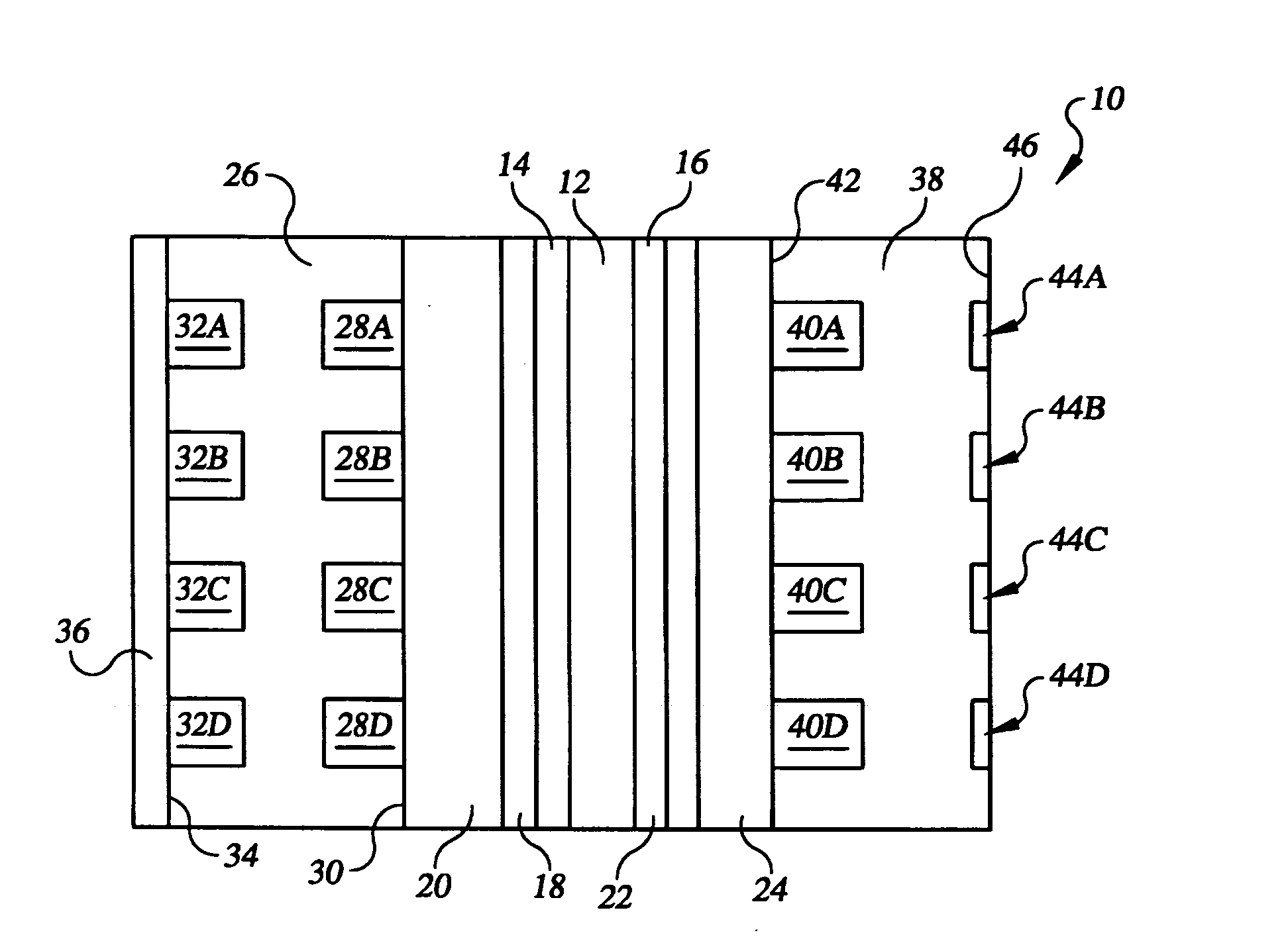
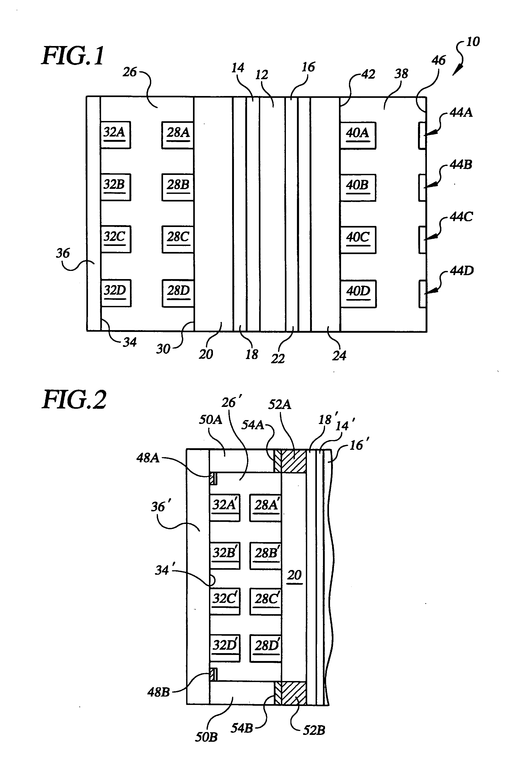
[0021] Referring to the drawings in detail, a fuel cell 10 is shown in FIG. 1 that is constructed in accordance with the present invention. The fuel cell 10 includes an electrolyte 12, such as a proton exchange membrane (“PEM”) secured between an anode catalyst 14 and a cathode catalyst 16 in a manner well known in the art. A porous anode diffusion layer 18 is secured adjacent the anode catalyst 14 and a porous anode substrate 20 is secured adjacent the diffusion layer 18. In the preferred embodiment shown in FIG. 1, both the anode diffusion and substrate layers 18, 20 are utilized, and they typically consist of a carbon black-hydrophobic polymer and porous carbon-carbon fibrous composite layers well known in the art as described in the aforesaid patents. However, in alternative embodiments, the anode catalyst 14 may be supported by only one of the two layers 18, 20. Additionally, at least one of the anode diffusion layer 18, the anode substrate layer 20 or both layers may be wetpro...


PUM

PropertyMeasurementUnit
concentrationaaaaaaaaaa
pressureaaaaaaaaaa
pressureaaaaaaaaaa

Abstract

The plant (60) includes at least one fuel cell (10, 62) having a wetproofed anode support (20) and a cathode support (24) for directing reactant streams adjacent catalysts (14, 16). A porous anode cooler plate (26) has its fuel channels (28A, 28B, 28C, 28D) secured adjacent the anode support (20). A porous cathode water management plate (38) has its oxidant channels (40A, 40B, 40C, 40D) secured adjacent the cathode support (24). A direct antifreeze solution passes only through coolant channels (32A, 32B, 32C, 32D) of the anode cooler plate (26) so the solution cannot poison the catalysts (14, 16), while fuel cell product water flows passively through the water management plate (38) and water management channels (44A, 44B, 44C, 44D) defined in the plate (38) to humidify reactant streams and be discharged from the fuel cell (62).

Description

TECHNICAL FIELD [0001] The present invention relates to fuel cell power plants that are suited for usage in transportation vehicles, portable power plants, or as stationary power plants, and the invention especially relates to a fuel cell power plant having fuel cells cooled by a direct antifreeze solution and having water managed within the cells passively without use of a water circulating pump. BACKGROUND ART [0002] Fuel cell power plants are well known and are commonly used to produce electrical current from hydrogen containing reducing fluid fuel and oxygen containing oxidant reactant streams to power electrical apparatus such as power plants and transportation vehicles. In fuel cell power plants of the prior art, it is known that thermal and water management of fuel cells typically includes circulating a coolant through the fuel cells to remove heat during operation of the cells, and to add heat during a start-up procedure. It is also known to utilize porous water transport pl...

Claims


Application Information

Patent Timeline
Patent Type & Authority Applications(United States)
IPC IPC(8): H01M8/02H01M8/04H01M8/24
CPCH01M8/0202H01M8/04029H01M8/04074Y02E60/50H01M8/04104H01M8/04119H01M8/241H01M8/04089
Inventor BREAULT, RICHARD D.
Owner INT FUEL CELLS
Why Eureka
Try Eureka