Color filter comprising retardation control layer, method for manufacturing the same, and display

a retardation plate and color filter technology, applied in the direction of identification means, instruments, polarising elements, etc., can solve the problems of reddish purple color, light reflection, and the thickness of the retardation plate is not negligibl

Active Publication Date: 2005-06-30
DAI NIPPON PRINTING CO LTD
View PDF12 Cites 73 Cited by
  • Summary
  • Abstract
  • Description
  • Claims
  • Application Information

AI Technical Summary

Benefits of technology

[0027] According to the present invention, a plurality of light transmission patterns different in thickness depending on color is formed on a substrate, to form a color filter, and a retardation control layer consisting of a liquid crystalline polymer is formed as one continuous layer on the color filter, and thus the thickness of the retardation control layer can be changed for the light transmission pattern of each color without adding any special process.

Problems solved by technology

As the retardation control layer in such a display, a stretched polycarbonate film, or a retardation control film obtained by applying a liquid crystalline material having birefringence anisotropy onto a triacetyl cellulose film or the like, is used, but an adhesive layer used in attaching the retardation control layer to a linear polarizing plate to form a laminate or in further attaching the laminate to a laminate display may cause light reflection, and the thickness of the retardation plate is not negligible.
Accordingly, a linear retardation plate and a retardation plate having a retardation of 138 nm are usually used in order to realize circularly polarized light in green of highest visibility, but deviation from circularly polarized light occurs in a narrow sense in red and blue so that when a mirror surface is observed via a circularly polarizing plate made of this retardation plate under a white light source, reddish purple color is observed due to leakage of red and blue lights, which is problematic upon use in prevention of reflection.

Method used


Image

  • Color filter comprising retardation control layer, method for manufacturing the same, and display
  • Color filter comprising retardation control layer, method for manufacturing the same, and display
  • Color filter comprising retardation control layer, method for manufacturing the same, and display

Examples


example 1

Color Filter with Circularly Polarized Light Functions

[0081] Each photosensitive resin composition (referred to hereinafter as photoresist) for forming a black matrix formed on a substrate or each color pattern of color filter layer was prepared. Each photoresist was prepared by adding beads to a pigment, a dispersant and a solvent and dispersing the mixture for 3 hours with a paint shaker as a dispersing machine, removing the beads to give a dispersion, and mixing the dispersion with a resist composition consisting of a polymer, a monomer, an additive, initiators and a solvent. The composition of each photoresist is shown below. The “parts” is expressed on a weight basis.

Black pigment14.0 parts(TM Black #9550 manufactured by DainichiseikaColor & Chemicals Mfg. Co., Ltd.)Dispersant 1.2 parts(Disper Big 111 manufactured by BYK Chemie Japan K.K.)Polymer 2.8 parts((Meth)acrylate resin VR60 manufactured by SHOWAHIGHPOLYMER CO., LTD.)Monomer 3.5 parts(Multifunctional acrylate SR399 ma...

example 2

Color Filter Having Retardation Control Functions for Vertically Oriented Mode Liquid Crystalline Display

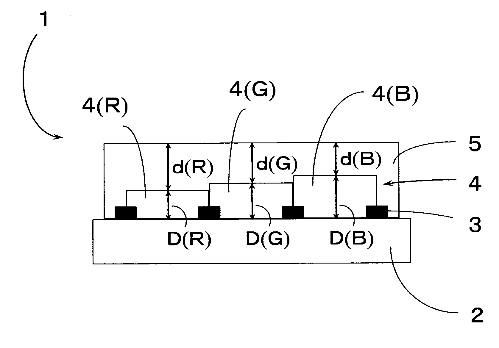
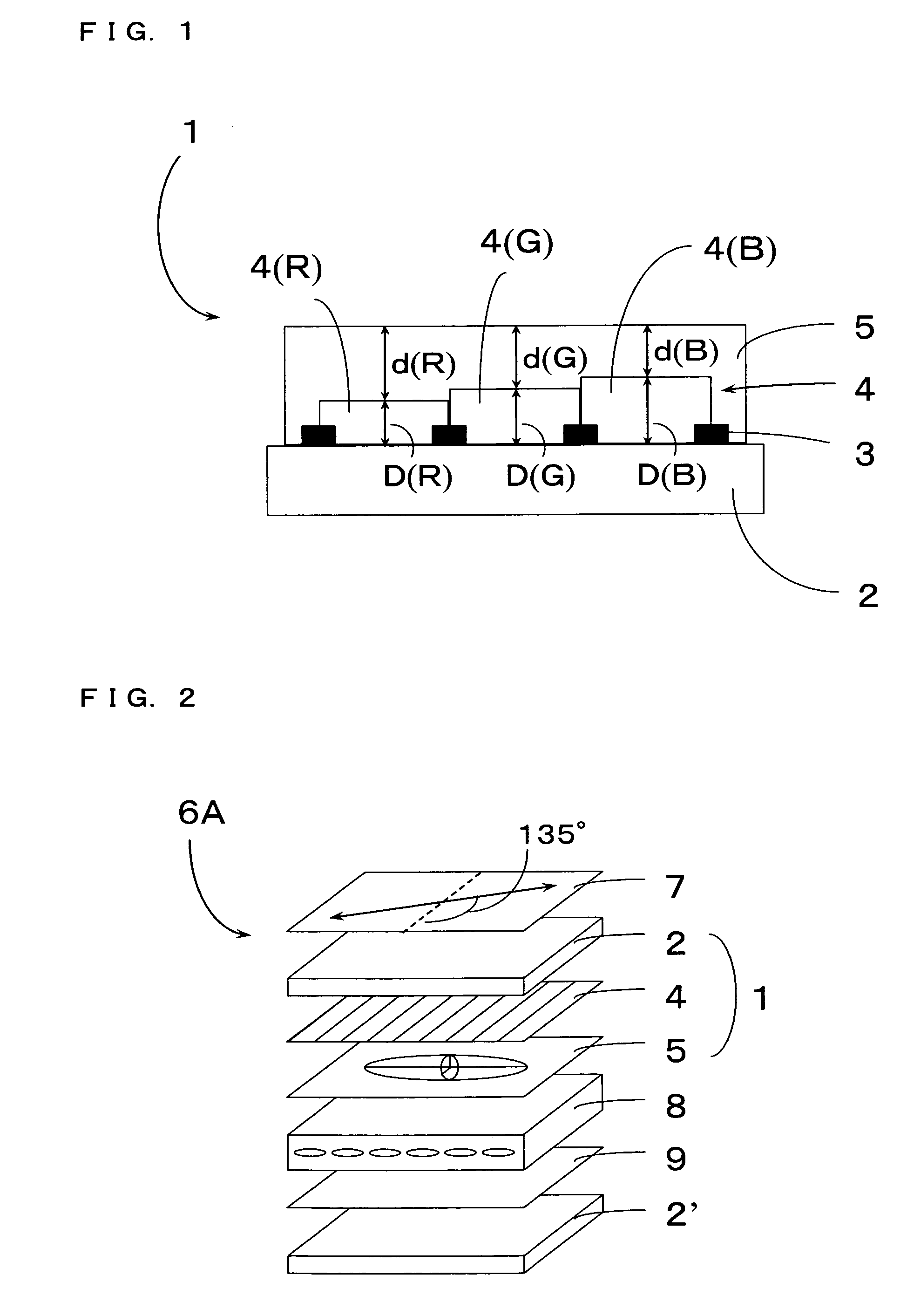
[0092] A color filter layer consisting of color patterns, that is, a red pattern of 2.4 μm in thickness, a green pattern of 2.6 μm in thickness, and a blue pattern of 2.9 μm in thickness, was formed in the same manner as in Example 1. In the photoresists for forming these color patterns, the amounts of the pigments blended in Example 1 were regulated to attain even spectral properties.

[0093] Using the photosensitive resin composition (1) used in Example 1, a first retardation control layer (1) (positive A plate) having a thickness of 0.86 μm on the red pattern, a thickness of 0.70 μm on the green pattern and a thickness of 0.50 μm on the blue pattern was formed on the color filter layer in the same manner as in Example 1. Using the photosensitive resin composition (2), a second retardation control layer (2) (negative C plate) having a thickness of 2.4 μm (measured on the green ...

example 3

Color Filter Shown in FIG. 7

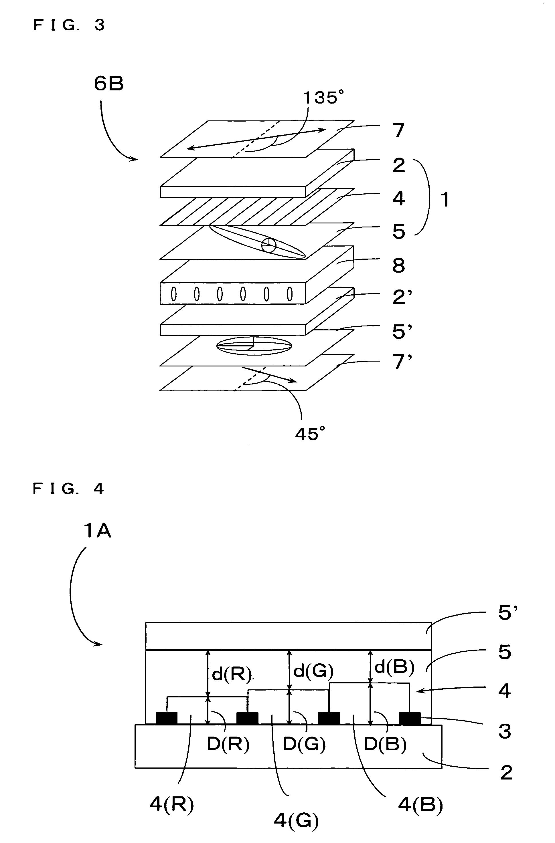
[0095] A color filter layer consisting of color patterns, that is, a red pattern of 2.8 μm in thickness, a green pattern of 2.6 μm in thickness and a blue pattern of 2.3 μm in thickness, was formed in the same manner as in Example 2. Using the photosensitive resin composition (2), a retardation control layer (negative C plate) having a thickness of 2.3 μm on the red pattern, a thickness of 2.4 μm on the green pattern and a thickness of 2.6 μm on the blue pattern was formed on the color filter layer.

[0096] By the color filter accompanied by the negative retardation control layer thus obtained, the retardation of the negative C plate is optimized with respect to red, green and blue, thus enabling reduction in wavelength scattering.


PUM

PropertyMeasurementUnit
central wavelengthaaaaaaaaaa

Abstract

The thickness of a retardation layer made of a liquid crystalline polymer used in improving visibility in a liquid crystalline display or the like is changed every color pattern of a color filter layer laminated with the retardation layer without adding a special process therefor to realize retardation suitable for each color pattern as the problem of the invention. This problem is solved in the invention by making the total thickness of the layers 4 and 5 constant in a structure having black matrix 3, color filter layer 4 and retardation control layer 5 laminated on substrate 2, and changing the thickness of the color filter layer 4 depending on each pattern, such that each region of the retardation control layer 5 has predetermined thickness.

Description

BACKGROUND OF THE INVENTION [0001] 1. Field of the Invention [0002] The present invention relates to a color filter comprising a retardation control layer for improvement of reflection prevention properties or viewing angle and suitable for indicating various displays particularly liquid crystalline displays in color, as well as a method for manufacturing the same. The present invention relates to a display constituted of the color filter comprising a retardation control layer. [0003] 2. Description of the Related Art [0004] Various types of displays have been practically used, and these displays are applied often by combining a retardation control layer with a linear polarizing plate or the like. For example, a circularly polarizing plate consisting of a combination of a linear polarizing plate and a ¼ wavelength retardation plate or a combination of a ½ wavelength retardation plate, a ¼ wavelength retardation plate and a linear polarizing plate is arranged at the observation side ...

Claims


Application Information

Patent Timeline
Patent Type & Authority Applications(United States)
IPC IPC(8): G02B5/20G02B5/30G02F1/1333G02F1/1335G02F1/13363G02F1/137G09F9/30H01L51/50H05B33/12H05B33/14
CPCG02B5/201G02B5/3083G02F1/133514G02F1/13363G02F2413/09G02F2001/133565G02F2001/133633G02F2201/48G02F2413/02G02F2001/133388G02F1/133388G02F1/133565G02F1/133631G02F1/133633
Inventor MORIYA, NORIHISA
Owner DAI NIPPON PRINTING CO LTD
Why Eureka
Try Eureka