Laser-guided coordination hole drilling

a laser-guided, coordination hole technology, applied in the direction of transportation and packaging, portable drilling machines, manufacturing tools, etc., can solve the problems of difficult adjustment, difficult adjustment, and difficulty in setting up, so as to reduce drilling accuracy, reduce drilling, and large numerical control

Active Publication Date: 2005-07-07
THE BOEING CO
View PDF38 Cites 94 Cited by
  • Summary
  • Abstract
  • Description
  • Claims
  • Application Information

AI Technical Summary

Benefits of technology

[0005] A laser-guided coordination hole drilling apparatus is provided. A laser-guided coordination hole drilling apparatus of certain advantageous embodiments of the present invention is portable and does not require large or massive foundations and may be manual, semi-automatic, or automatic. A laser-guided coordination hole drilling apparatus of one embodiment of the present invention includes a positioning table that allows movement in at least one plane, typically the x-y plane; a bushing cavity for receiving a target bushing and drill bushings; a clamping device, typically screw clamps or vacuum cups, for securing the positioning table to a part into which holes will be drilled; and a laser target on the positioning table, typically proximate to the bushing cavity or in a target bushing recessed in the bushing cavity, for allowing a laser tracker to locate the position of the positioning table and bushing cavity.
[0006] An x-y positioning table of an embodiment of the present invention may include manual screw adjustments for movement in the x- and y-axes or automatic motors, such as servomotors, for movement in the x- and y-axes. A laser target for an embodiment of the present invention may be an open-air, corner-cube optical target or other retroreflector. An embodiment of a laser-guided coordination hole drilling apparatus of the present invention may include two-staged, concentric vacuum cups for rigidly affixing the positioning table to a part into which a hole will be drilled. Another embodiment of a laser-guided coordination hole drilling apparatus of the present invention may be designed to allow the positioning table to drill holes at an angle to a drill motor mounted to the positioning table. Alternatively, a positioning table of an embodiment of the present invention may be a dual rotating nonconcentric positioning table.
[0011] An embodiment of a system for drilling coordination holes of the present invention may include a movement monitoring routine of the software program interoperably connected to the laser tracker and / or a software interlock routine interoperably connected to the drilling apparatus, drill bushing, or drill motor. These subroutines of the software program may prevent accidental drilling of a hole at an improper location.
[0012] Embodiments of the present invention are more suitable for machining coordination holes on numerous types of parts and on parts of various shapes and sizes. The size of a drilling apparatus of the present invention provides flexibility to drill or machine coordination holes in parts at positions that would otherwise be difficult or impossible to machine with a large numerically controlled machine even if the part were re-oriented for the large numerically controlled machine. Embodiments of the present invention further provide the ability for parallel drilling, where more than one machining operation is performed on a part at one time. The size of a drilling apparatus of the present invention also eliminates the need for a large work environment, which may reduce drilling accuracy, required for a large numerically controlled machine.

Problems solved by technology

These machines are also expensive, difficult to set up, not easily moved, and hard to modify.
In addition, the weight of a machine and the large work environment decrease the accuracy of drilling.
In effect, the present method of drilling coordination holes in large parts is inflexible.
In addition, the present method of drilling coordination holes, using a large numerically controlled machine on a massive foundation, is not suited for drilling coordination holes in higher-level assemblies, such as wing boxes and assembled structures because in part due to the machine's inability to access smaller or internal recesses.
Configuring and adapting a large numerically controlled machine for many different parts is time consuming and labor intensive, making using a large numerically controlled machine on a massive foundation an impracticable solution for drilling coordination holes with many types of parts.

Method used


Image

  • Laser-guided coordination hole drilling
  • Laser-guided coordination hole drilling
  • Laser-guided coordination hole drilling

Examples


first embodiment

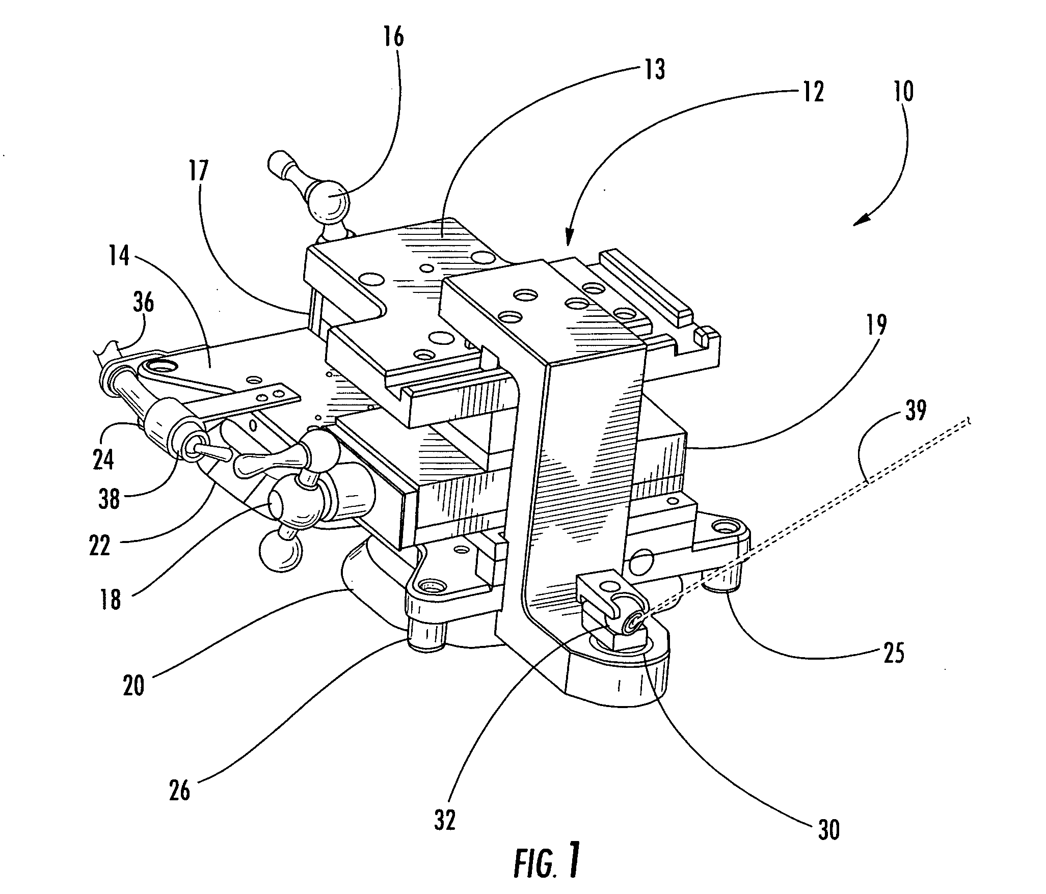
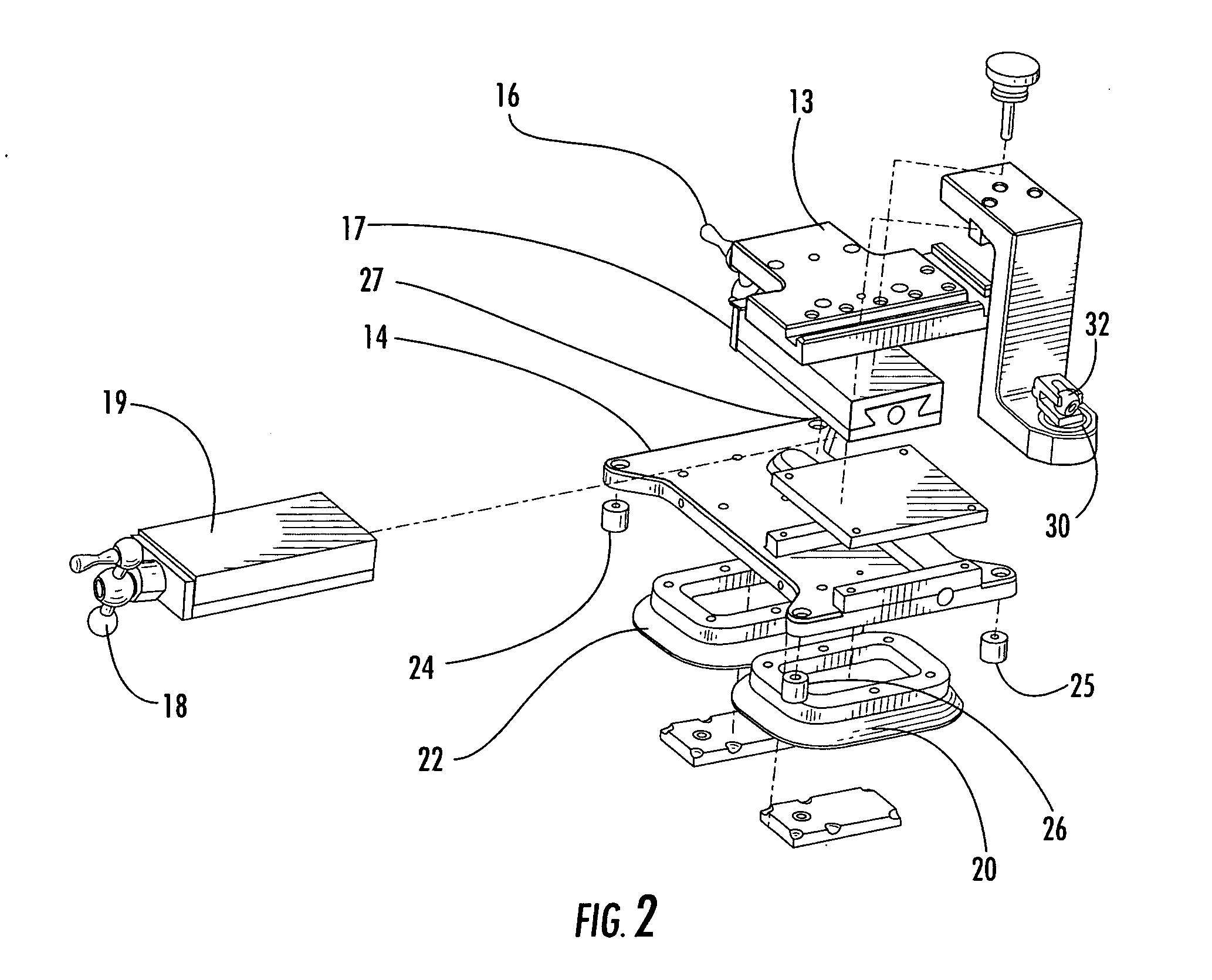
[0030]FIG. 1 is a perspective view of a coordination hole drilling apparatus of the present invention, which may also be referred to as a coordination hole tool or a laser drill jig. A drilling apparatus 10 of one embodiment of the present invention includes an x-y positioning platform or table 12. A positioning platform 12 allows for movement of a moveable portion 13 of the platform along one or more axes while a foundation portion 14 of the platform remains stable. An x-y positioning platform provides for movement along orthogonal axes, the x- and the y-axes. The movable portion 13 of a positioning platform for a drilling apparatus 10 of the present invention defines at least a bushing cavity 30 for accepting bushings to hold a laser target 32 or receive different sized tools.

[0031] A positioning platform 12 may be supported by legs or feet 24 upon which the drilling apparatus 10 may rest against a part. Typically, the positioning platform 12 is in an approximately parallel plane ...

third embodiment

[0035]FIG. 4 is a perspective view of a coordination hole drilling apparatus 60 of the present invention. The embodiment shown in FIG. 4 is an example of a coordination hole drilling apparatus of the present invention that includes screw clamps 66, 68 to rigidly affix the drilling apparatus 60 to a part.

[0036]FIG. 5 is a schematic diagram showing vacuum cups 20, 22 of the coordination hole drilling apparatus 10 of FIGS. 1 and 2. Vacuum cups allow a drilling platform of the present invention to easily be positioned on a part, even against the pull of gravity, such as drilling upside down. The vacuum cups 20, 22 of this embodiment are two-staged, concentric vacuum cups for rigidly affixing the positioning table to a surface on the part. A two-stage vacuum cup provides a low vacuum for positioning and a high vacuum for providing additional stability during drilling. However, as exemplified by the screw clamps 66, 68 in the third embodiment shown in FIG. 4, any type of clamping device t...

fourth embodiment

[0037]FIG. 6 is a perspective view of a coordination hole drilling apparatus 70 of the present invention. The embodiment shown in FIG. 6 is a more compact version of a drilling apparatus of the present invention. This embodiment is just one more example of the variety of design possibilities for creating a drilling apparatus of the present invention. The drilling apparatus is typically designed based upon the intended use and application. For example, a smaller device may be more practical for delicately drilling smaller holes or repeatedly moving the drilling apparatus to drill a large plurality of holes. Conversely, a larger drilling platform may be beneficial for drilling applications that require more force or drilling a smaller number of holes. Regardless of the application, a drilling apparatus of the present invention may be designed and made from appropriate materials to provide appropriate hardness, stiffness, and accuracy for precision hole drilling, such as granite, tungs...


PUM

PropertyMeasurementUnit
diameteraaaaaaaaaa
diameteraaaaaaaaaa
diametersaaaaaaaaaa

Abstract

A laser-guided coordination hole tool for precisely drilling holes in large parts includes a positioning table, a bushing cavity for receiving drill bushings, a clamping device, and a laser target. A laser-guided coordination hole tool may include a software interlock to prevent drilling in an improper location on the part. A method of drilling coordination holes includes probing a part to determine its reference frame, rigidly affixing a laser-guided coordination hole tool to the part, probing a target on the laser-guided coordination hole tool to determine the reference frame for the laser-guided coordination hole tool, accurately positioning a drill bushing over the hole location, and drilling a hole. A system for drilling coordination holes includes a laser-guided coordination hole tool, a bushing, a tooling, a drill motor, a laser tracker, and a computer running a coordination-hole drilling program.

Description

FIELD OF THE INVENTION [0001] The present invention relates generally to coordination hole drilling, and, more particularly, to coordination hole drilling of large production parts such as those constructed and assembled for aircraft or ships. BACKGROUND OF THE INVENTION [0002] One activity which must be performed when building with large component parts, such as when building an aircraft or during shipbuilding, is drilling holes at various locations in these large parts. Such holes may be referred to as coordination holes because they are located at coordinate locations measured on the parts. The coordination holes are then used to affix a part to another part with corresponding coordinating holes such as by putting a fastener thru to hold multiple parts together. Each time the same part is replicated, coordination holes must be measured and drilled in the same locations, often requiring precise measurements and accuracy of drilling. [0003] The present method of achieving the accur...

Claims


Application Information

Patent Timeline
Patent Type & Authority Applications(United States)
IPC IPC(8): B23Q3/18B23Q9/00B23Q17/22B23Q17/24
CPCB23B2215/04B23Q3/183B23Q17/22B23Q17/24Y10T409/306384Y10T408/553Y10T408/175Y10T408/03Y10T408/554Y10T408/56245
Inventor CLARK, GREGORY L.
Owner THE BOEING CO
Why Eureka
Try Eureka