
Burner head and gas burning appliance provided with such a burner head

a burner head and burner head technology, which is applied in the direction of burners, burner manufacture, combustion types, etc., can solve the problems of affecting the process yield, difficult to provide stable and exact formation, and relative hardness and poor workability, so as to improve the process yield, high workability characteristics, and the effect of stabilizing not only

Inactive Publication Date: 2005-12-27
NORITZ CORP
View PDF18 Cites 1 Cited by
  • Summary
  • Abstract
  • Description
  • Claims
  • Application Information

AI Technical Summary

Benefits of technology

[0006]Bearing mind in the above-described circumstances, the present invention was made. Accordingly, a major object of the present invention is to provide a burner head and gas burning appliance capable of making the ensuring of heat resistance and durability characteristics compatible with the improvement in the quality of machining, capable of easily and stably machining a material into a complicated shape, and capable of reducing the cost of production.
[0009]In accordance with the first invention, the plate member used to form a burner head is formed of metal primary materials having characteristics suitable for a region for formation of a burner port and for a region for formation of a gas passage respectively. Stated another way, the burner-port constituting region is comprised of a metal primary material of high heat resistance and, on the other hand, the gas-passage constituting region is comprised of a metal primary material suitable for machining of a complicated shape. As a result of such arrangement, while allowing the burner head to maintain adequate heat resistance and durability characteristics, it is possible to form a complicated shape with accuracy and ease. Therefore, it becomes possible to manufacture and provide a high-performance, high-quality burner head. Besides, it is unnecessary to use an expensive metal primary material of high heat resistance for the entire plate member. Lowering the cost of material reduces the cost of production.
[0011]In an example of an embodiment of the first invention, the metal flat-plate material comprises a combination of a first metal primary material having high heat resistance and a second metal primary material having high workability characteristics, and the burner-port constituting region (for example, the burner port and regions in the vicinity of the burner port) and the gas-passage constituting region are formed, by press molding, in a first section of the metal flat-plate material which is formed of the first metal primary material and in a second section of the metal flat-plate material which is formed of the second metal primary material, respectively. As a result of such arrangement, it becomes possible to realize the characteristics of a metal primary material to be selected according to each of the burner-port and gas-passage constituting regions. This further ensures realization of the operation / working-effect of the present invention.
[0012]Furthermore, the metal flat-plate material, used to form a plate member of a burner head of the present invention, is concretely specified in the light of its manufacture method. The metal flat-plate material is manufactured by uniting, by means of butt welding, different types of plate-like metal primary materials at end edges thereof in the same plane. This ensures formation of a metal flat-plate material by the use of different types of metal primary materials of different characteristics for each region. Furthermore, a butt welding operation in this case will be specified. End edges of each of the plural plate-like metal primary materials extend straightway, and it is set such that a butt-welding region of the metal flat-plate material extend straightway, and it is set such that the butt-welding region is located at such a position between the burner-port constituting region and the gas-passage constituting region that the variation in shape of each of the burner-port and gas-passage constituting regions becomes minimum. This makes it possible to stabilize not only the quality of a section of the metal flat-plate material extending as the butt-welding region but also the quality of a plate member having a welding region. Besides, possible harmful effects due to the presence of a butt-welding region are also eliminated. Furthermore, as the foregoing butt welding, TIG (Tungsten Insert Gas) arc welding may be employed. Also, laser welding may be employed. Since the above-described welding technique in which base metals of metal primary materials are melted and welded together is employed, this makes it possible to form a plate member using only the original metal primary material which does not contain materials such as welding materials.
[0013]A second invention provides a problem-solving means which relates to a gas burning appliance. The gas burning appliance of the second invention employs a burner head according to the first invention which has been described as a gas burning appliance. In accordance with the second invention, the burner head maintains resistance to high heat and durability characteristics and is provided with a gas passageway formed with high dimensional accuracy because of the improvement in workability. This makes it possible to provide a gas burning appliance of stable combustion performance quality. In addition, by virtue of lowering the cost of production of a burner head, the total cost of production of a gas burning appliance is also reduced.

Problems solved by technology

This means that complicated recessed portions and recessed grooves for forming burner ports, gas passages, and so on must be formed by press molding of the above-described material which is relatively hard and poor in workability.
This accordingly causes difficulties in providing stable and exact formation of a gas passage having a complicated shape.
In addition, the occurrence of cracking may cause impairment of the process yield.
Furthermore, the material used is costly, thereby increasing the production cost (material cost) of a burner head, and the production cost of gas burning appliances provided with a burner head is likely to increase.

Method used


Image

  • Burner head and gas burning appliance provided with such a burner head
  • Burner head and gas burning appliance provided with such a burner head
  • Burner head and gas burning appliance provided with such a burner head

Examples


Embodiment Construction

[0019]Hereinafter, embodiments of the present invention will be described with reference to the drawings.

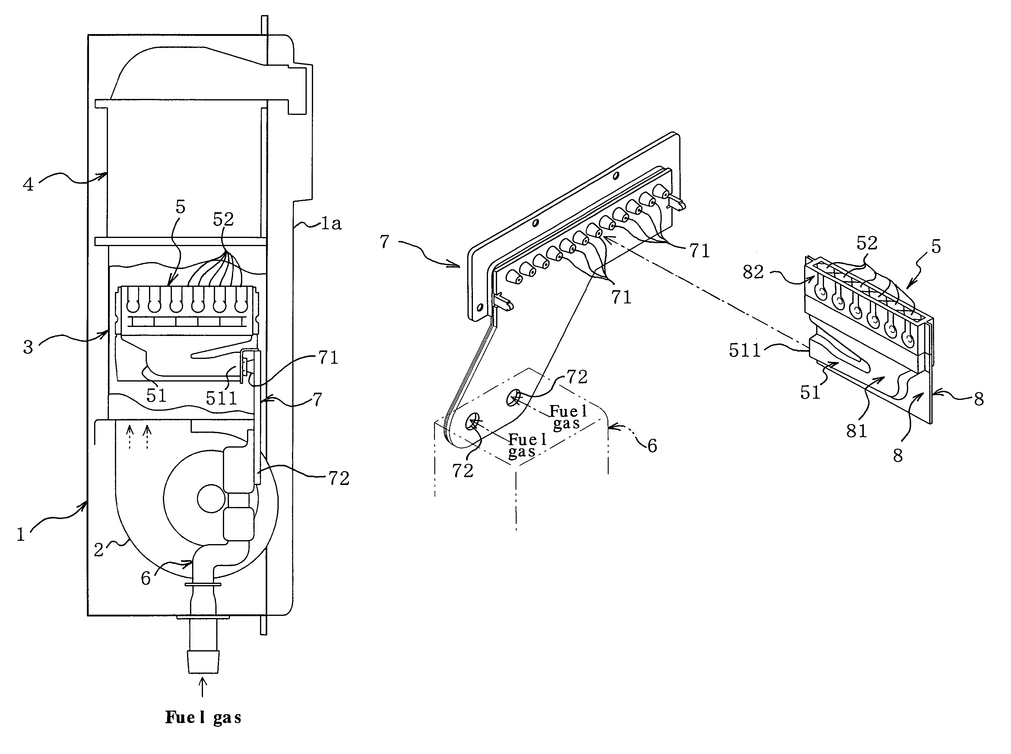
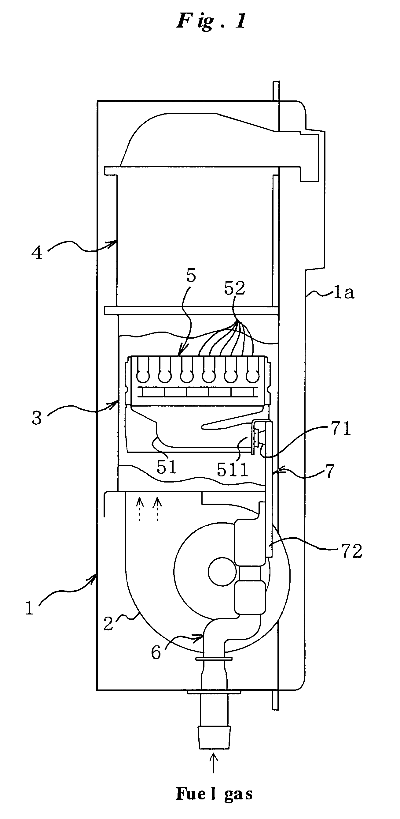
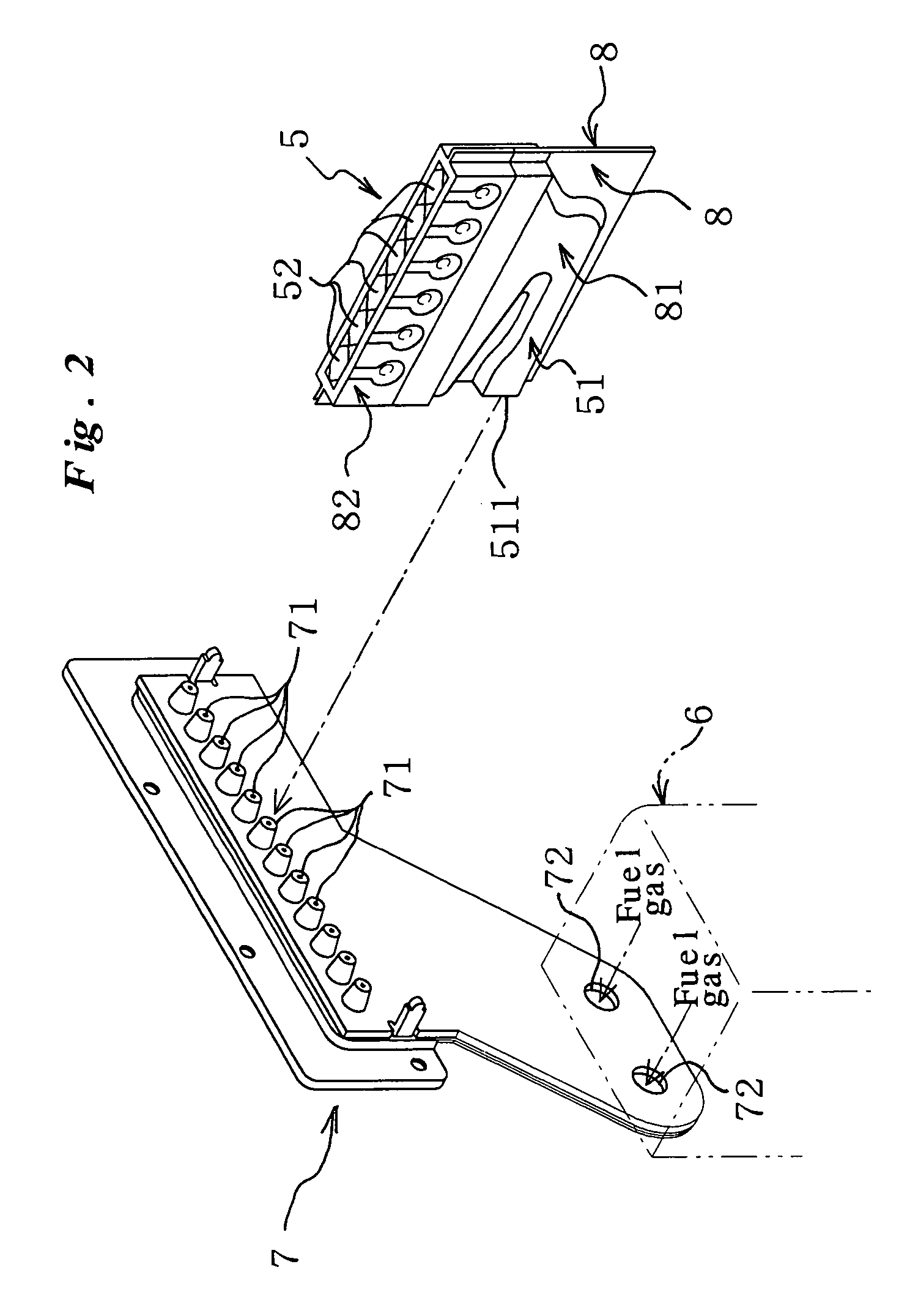
[0020]Referring first to FIG. 1, there is shown an instantaneous gas water heater as a gas burning appliance provided with a burner head according to an embodiment of the present invention. The reference numeral 1 denotes a housing. The reference numeral 1a denotes a front cover of the housing 1. The reference numeral 2 denotes a air blower fan for supplying air for combustion. The reference numeral 3 denotes a combustion storage water heater body in which is contained a combustion burner. The reference numeral 4 denotes a heat exchange storage water heater body disposed above the combustion storage water heater body 3 and containing therein piping of a heat exchanger (not shown). Tap water is fed into the heat exchanger. Hot water heated by combustion heat in the combustion storage water heater body 3 is supplied to a hot water tap or the like.

[0021]A predetermined number of bur...


PUM


Abstract

Disclosed is a burner head capable of securing heat resistance and durability characteristics and improving the quality of machining at the same time, capable of easily and stably machining a material into a complicated shape. A second metal primary material of the iron family having high workability and first metal primary materials of the SUS family having high heat resistance are rolled out. Their side plate ends are butt-welded by laser to form a one-piece metal flat-plate material. A press molding machine is operated to press mold recessed portions of a pair of plate members simultaneously with cutting along a contour line. Then, folding is carried out, and they are closely joined together. A gas passage is formed by a recessed portion of the second metal primary material section. A burner port is formed by a recessed portion of the first metal primary material section.

Description

BACKGROUND OF THE INVENTION[0001]1. Field of the Invention[0002]The present invention generally relates to a burner head for use in gas burning appliances such as water heaters, combustion equipment, et cetera. This invention relates more particularly to a burner head formed by joining together press-molded metal plate materials.[0003]2. Description of the Related Art[0004]It is well known in the prior art to form a burner head for use in gas burning appliances, first by superimposing inner and outer plates to be disposed interiorly and then by joining together the plates to a unit by means of spot welding or laser welding from the side (see Japanese Patent laid open Gazette No. 7(1995)-158822). More specifically, the inner and outer plates are each formed by press molding a sheet of metal material plate and the thus press-molded metal material plates are placed one over the other and are assembled together. Thereafter, the plates are welded together in the way as described above.SU...

Claims


Application Information

Patent Timeline
IPC IPC(8): F23D14/08F23D14/04F23D14/10
CPCF23D14/045F23D14/105F23D2213/00F23D2900/14641
Inventor IKUTA, MINORUUEHARA, KOZOTANBA, SHUNJINAKAMURA, AKINOBU
Owner NORITZ CORP
Learn More