Sterilizing apparatus and sterilizing method

a technology of sterilizing apparatus and endoscope, which is applied in the field of sterilizing apparatus and sterilizing method, can solve the problems of insufficient contact between the sterilization steam and the surface, damage to electronic components built in the endoscope, and inability to achieve full sterilization effect, so as to prevent degradation of the endoscope

Inactive Publication Date: 2005-07-07
OLYMPUS CORP
View PDF9 Cites 103 Cited by
  • Summary
  • Abstract
  • Description
  • Claims
  • Application Information

AI Technical Summary

Benefits of technology

[0034] In the invention, information relating to the type, history, etc. of a to-be-sterilized object is stored. Based on the information, the process condition is automatically set and confirmed, and correction is made to the to-be-sterilized object. According to the invention, it is possible to prevent degradation in an endoscope due to variations in a sterilizing process.

Problems solved by technology

If contamination on the endoscope is not removed, steam for sterilization does not sufficiently come in contact with that part of the surface of the endoscope, where contamination is present, in a process of sterilizing the endoscope by means of a sterilizing apparatus.
Consequently, the effect of sterilization cannot fully be obtained.
Besides, if there is a hole or a flaw in the endoscope, electronic components that are built in the endoscope would be damaged by exposure to high-pressure steam.
However, the user has to check whether the endoscope has undergone the cleaning process and leak check.
However, as will be described later, the work of exactly inputting information associated with the conditions of individual endoscopes is complex and time-consuming due to peculiar problems of endoscopes.
The load on the user side is great, and the user is required to have relatively high-level expertise.
Such endoscopes require a considerable length of time for a sterilizing process until steam for sterilization reaches all parts of the channels.
In the case of an endoscope having no channels or a short, thick endoscope with a simple channel structure, steam can reach all parts of channels in a short time period and a process time may be short.
Noise, etc. may be included in an image, and the quality of the image may deteriorate.
However, if proper settings are not made, the endoscope may be damaged in the sterilizing process and the durability of the endoscope may be degraded.
If much moisture remains in the endoscope, the durability of the endoscope tends to decrease.
However, the addition of an excessive drying step leads to an increase in process time and is disadvantageous when a quick process is needed.

Method used


Image

  • Sterilizing apparatus and sterilizing method
  • Sterilizing apparatus and sterilizing method
  • Sterilizing apparatus and sterilizing method

Examples


first embodiment

(First Embodiment)

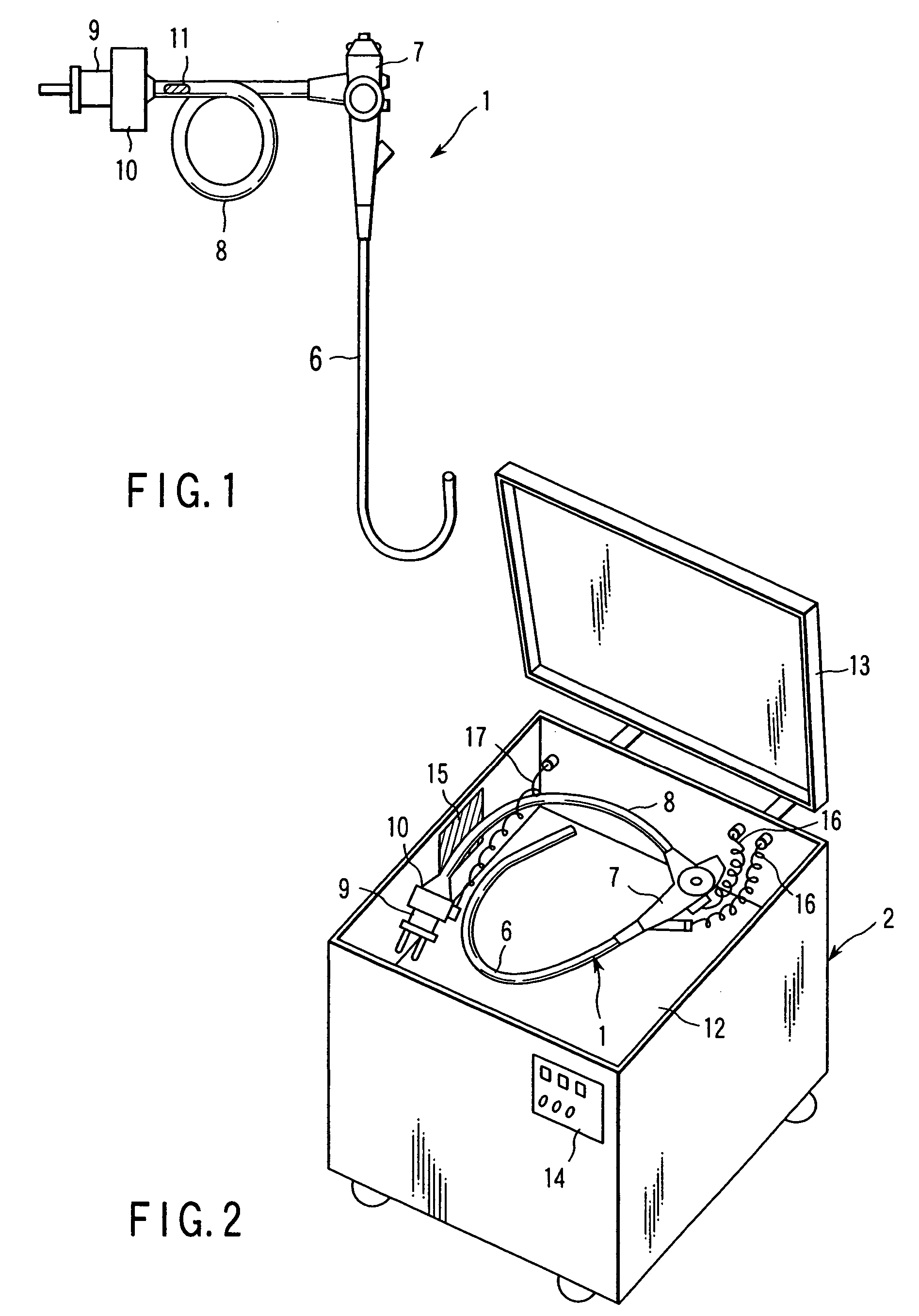
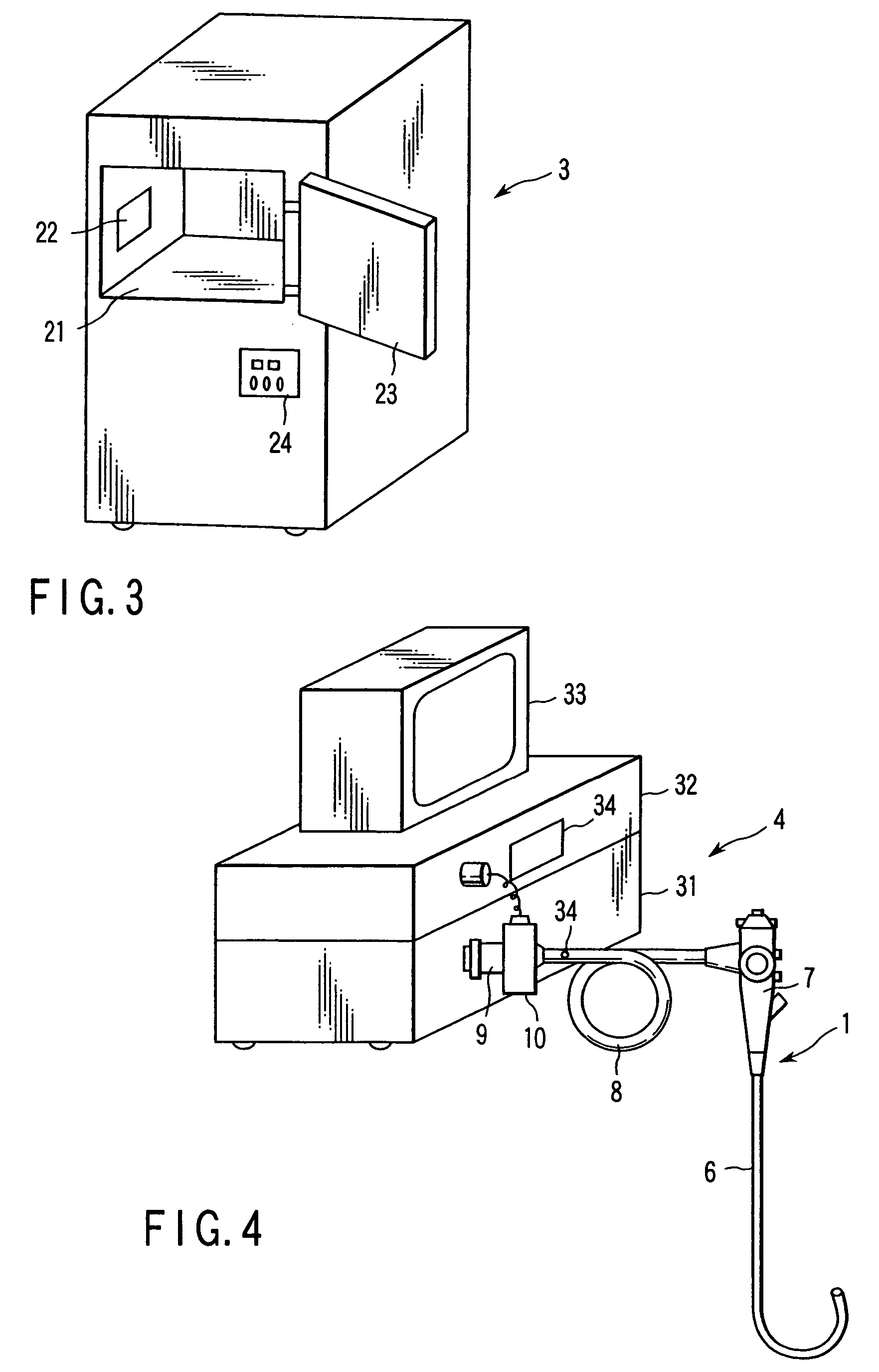
[0048] An endoscope cleaning apparatus according to a first embodiment of the invention will now be described with reference to FIG. 1 to FIG. 6. FIG. 1 schematically shows an endoscope 1. FIG. 2 shows an endoscope cleaning apparatus 2 for cleaning the endoscope 1. FIG. 3 shows an endoscope sterilizing apparatus 3 for sterilizing the endoscope 1. FIG. 4 schematically shows an endoscopy system 4. FIG. 5 is a block diagram of the endoscopy system 4, and FIG. 6 is a circuit diagram of an RFID unit and an RFID tag.

[0049] The endoscope 1 includes an insertion section 6, an operation section 7 and a light guide cable 8. A connector 9 is provided at an extension end of the light guide cable 8. A communication connector section 10 for electrical connection to a peripheral device (not shown) is provided in the vicinity of the connector 9. The communication connector section 10 is provided with a connector portion for leakage testing (not shown). The communication connector...

second embodiment

(Second Embodiment)

[0083] An autoclave apparatus according to a second embodiment of the invention will now be described with reference to FIG. 7 to FIG. 10. FIG. 7 is an explanatory view that schematically shows the structure of an endoscope. FIG. 8 is an explanatory view that schematically shows the structure of an autoclave apparatus for sterilizing the endoscope shown in FIG. 7. FIG. 9 is a time chart of an autoclave sterilization process using the autoclave apparatus shown in FIG. 8. FIG. 10 is a flow chart that illustrates the autoclave sterilization process by the autoclave apparatus shown in FIG. 8.

[0084] As is shown in FIG. 7, an endoscope apparatus 101 includes an endoscope 102 with imaging means; a light source device 103 that is detachably connected to the endoscope 102 and supplies illumination light to a light guide (not shown) that is provided on the endoscope 102; a video processor 105 that is connected to the endoscope 102 via a signal cable 104, controls the imagi...

third embodiment

(Third Embodiment)

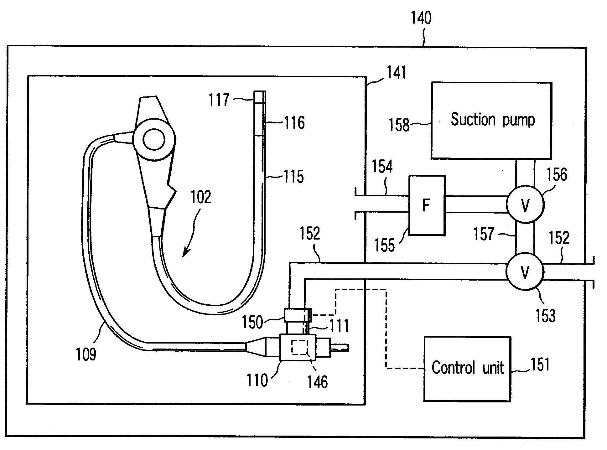
[0134] An autoclave apparatus according to a third embodiment is described referring to FIG. 11 and FIG. 12. The present embodiment is substantially the same as the second embodiment. Different points are mainly described. The common structural parts are denoted by like reference numerals, and a detailed description is omitted. FIG. 11 is an explanatory view that shows the structure of the autoclave apparatus that subjects the endoscope to autoclave-sterilization. FIG. 12 is a flow chart illustrating the flow of the autoclave process using the autoclave apparatus shown in FIG. 11.

[0135] As is shown in FIG. 11, in the present embodiment, an autoclave apparatus 140 and an endoscope cleaning apparatus 147 are connected to a central management apparatus 148 by a signal line 149. Specifically, the autoclave apparatus 140 itself does not execute data management and processing. The data management and processing are executed by the central management apparatus 148. As is...


PUM

PropertyMeasurementUnit
temperaturesaaaaaaaaaa
temperatureaaaaaaaaaa

Abstract

The invention is a sterilizing apparatus that reads information from an information recording section provided in an endoscope, sets a sterilizing process condition for sterilizing the endoscope on the basis of the read information, and controls a sterilizing process in accordance with the sterilizing process condition that is set.

Description

CROSS REFERENCE TO RELATED APPLICATIONS [0001] This is a Continuation Application of PCT Application No. PCT / JP02 / 09063, filed Sep. 5, 2002, which was published under PCT Article 21(2) in Japanese. BACKGROUND OF THE INVENTION [0002] 1. Field of the Invention [0003] The present invention relates to a sterilizing apparatus and a sterilizing method for sterilizing a to-be-sterilized object such as an endoscope. [0004] 2. Description of the Related Art [0005] After an endoscope is used in an inspection, the endoscope is cleaned by a cleaning apparatus to remove contamination on the endoscope. Subsequently, the endoscope is subjected to high-pressure steam in an autoclave apparatus, and the endoscope is sterilized to prevent infection. In this way, the cleaning and sterilization of the endoscope are independently performed by the different apparatuses. [0006] If contamination on the endoscope is not removed, steam for sterilization does not sufficiently come in contact with that part of ...

Claims


Application Information

Patent Timeline
Patent Type & Authority Applications(United States)
IPC IPC(8): A61B1/00A61B19/00A61B1/12A61L2/06A61L2/07A61L2/24A61L2/26
CPCA61B1/00059A61B1/123A61L2/24A61L2/07A61L2/06
Inventor NOGUCHI, TOSHIAKIMORIYAMA, HIROKIOSHIMA, RYUAMANO, SHOICHIISHIBIKI, KOTAMORISHITA, KOJIFUTATSUGI, YASUYUKIHASEGAWA, HITOSHINAKAGAWA, MIKIHIKOYOSHIMOTO, YOSUKETASHIRO, YOSHIO
Owner OLYMPUS CORP
Why Eureka
Try Eureka