
Low cost film composite can liner

a film composite and can liner technology, applied in the field of tubular composite container making methods and apparatuses, can solve the problems of difficult sealing, corroding foil, discoloring or otherwise adulterating products, and spoiling food products stored within containers, so as to eliminate the need for costly folding operations, reduce cost, and improve abrasion protection

Inactive Publication Date: 2005-07-14
SONOCO DEV INC
View PDF5 Cites 11 Cited by
  • Summary
  • Abstract
  • Description
  • Claims
  • Application Information

AI Technical Summary

Benefits of technology

[0019] The relatively low cost, HDPE layers bond with many sealants, including Surlyn® produced by Dupont, which is a preferred sealant according to the present invention. Suryln® and other ionomer resins have relatively low sealing or melting temperatures and thus can provide quick and efficient hermetic seals with a minimum of dwell time. Additionally, such resins accommodate a hermetic seal even through contamination, such as wax. Further, they are highly formable for easy winding during tube forming and FDA-approved for contact with food products.
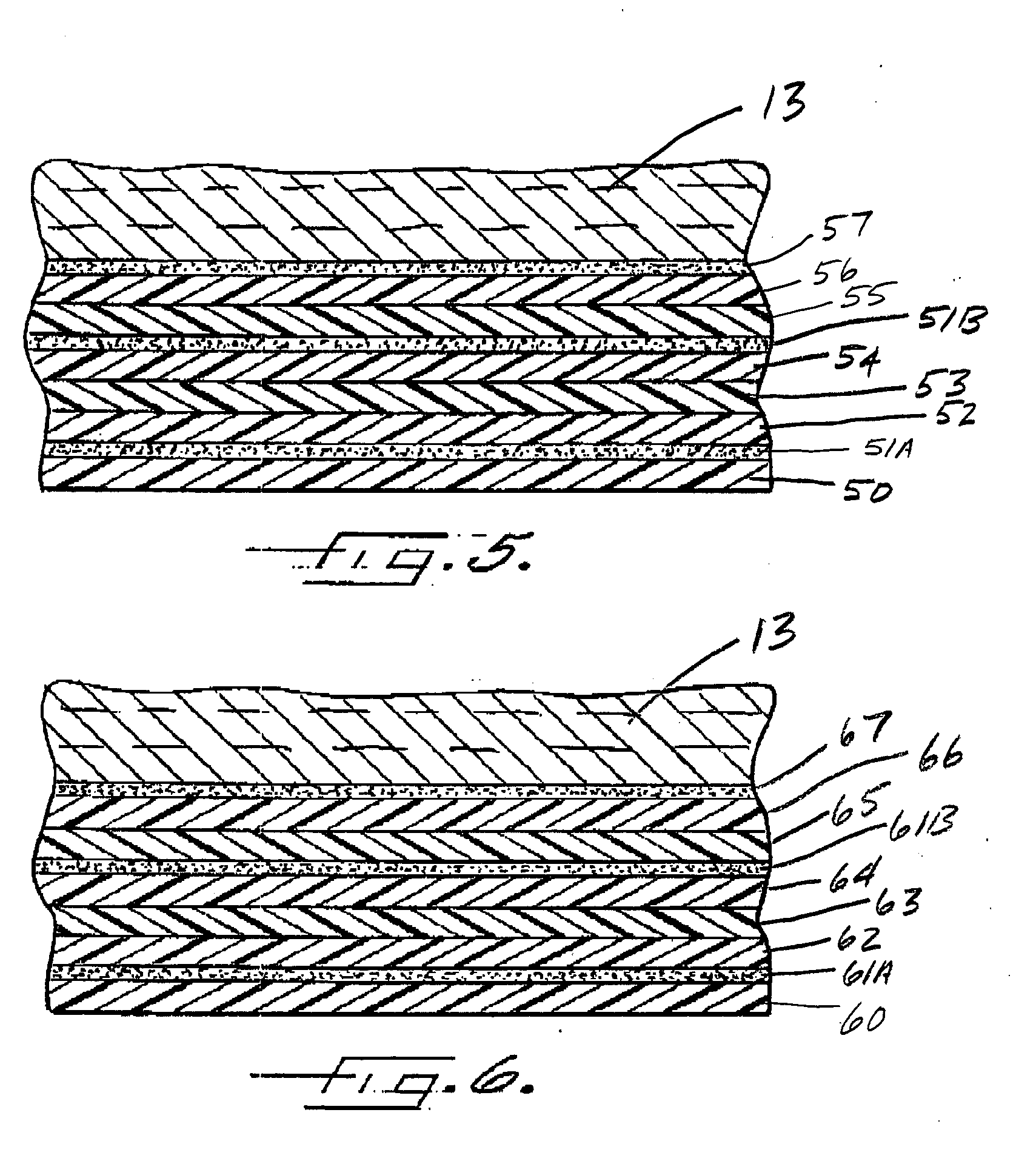
[0021] If wax is not used to hold the closure membrane in place, as is the case in newer tube forming machines where vacuum pressure replaces the wax, an HDPE or blended layer could be used as a sealant instead of Surlyn e, to further reduce cost. Accordingly, a liner ply having a mandrel-contacting sealing surface composed of HDPE or Surlyn® and an opposite compatible surface composed of HDPE, could readily be adhered together in overlapping fashion and thereby eliminate the need for costly folding operations.
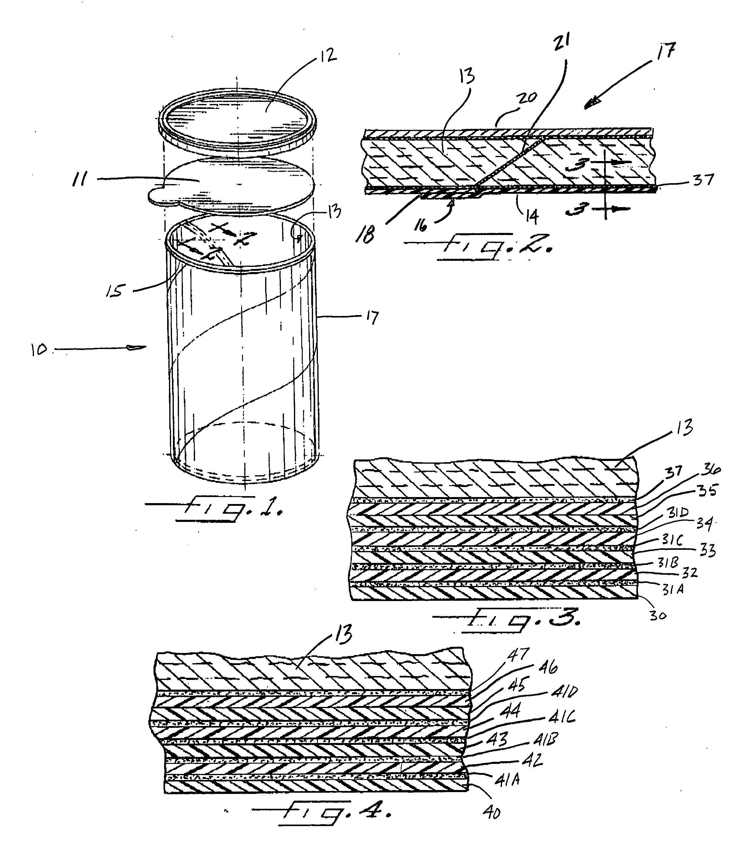
[0022] Sandwiched between the Surlyn® and HDPE layers are additional polymer layers comprised of polyamides and an ethylene / vinyl alcohol copolymer (EVOH). Preferred polyamides include nylon 6 and nylon 6 / 6, or the like as known to one of ordinary skill in the art. The polyamide layers provide improved abrasion protection from the food product contained within the container, such as from salt crystals in the case of potato chips. The ethylene / vinyl alcohol copolymer layer, in combination with HDPE and polyamide layers, provides significantly improved moisture vapor and oxygen barrier protection.
[0028] As mentioned above, should a wax binder prove unnecessary for the membrane sealing operation, a HDPE layer could be used in place of Surlyn® as the sealant layer so as to significantly reduce the cost of the liner. Accordingly, another preferred embodiment of the present invention comprises a tubular composite container having a co-extruded multilayer liner that includes a first high density polyethylene layer, a second tie layer, a third polyamide layer, a fourth tie layer, a fifth layer comprising an ethylene / vinyl alcohol copolymer, a sixth tie layer, a seventh polyamide layer, an eighth tie layer, a ninth high density polyethylene layer, and a tenth high density polyethylene layer. Once again, depending upon the application, the fourth and sixth tie layers may optionally be omitted producing yet another preferred embodiment of the present invention wherein the polyamide layers are bonded directly to the EVOH layer.

Problems solved by technology

Exposure to external moisture or gases could potentially spoil the food products stored within a container.
The polymeric layer prevents the food product from coming into contact with the foil layer, which in some cases can cause a reaction that can corrode the foil and discolor or otherwise adulterate the product.
Despite the benefits provided by the foil and kraft paper layers, it is desirable to produce liners that omit these layers, as they are expensive, difficult to seal, difficult to adhere additional layers to, and greatly increase the liner thickness.
Thus, with relatively thick supported liners (including kraft and foil layers), the anaconda fold seam presents difficulties when attempting to hermetically seal the ends of the tubular container.
However, in the area where the thick anaconda fold seam forms a portion of the end surface, the end surface of the bead or flange can be substantially non-planer thus forming hill-like and / or valley-like irregularities.
However, the apparatus used to laminate the body and liner plies together before wrapping the plies onto the mandrel may not be the most advantageous in some applications.
Additionally, it will be appreciated that both the liner supply and body ply supply rolls must be located on the same side of the mandrel, which can make the placement of the supply rolls and the routing of the plies to the mandrel more complicated than would otherwise be the case if both the liner and body plies did not have to approach the mandrel from the same side.
Replacement of the rolls may also be more difficult where the two supply rolls are located close together as they would tend to be in order to make efficient use of space.
With the method of the '004 patent, the heat-sealable material on the inner surface of the liner strip is heated and softened as it passes over the heated portion of the mandrel, and this softening leads to greater friction between the liner strip and the mandrel.
This friction, and resulting softening, could lead to “scuffing” of the polymer layer as it advances along the mandrel.
Unfortunately, however, providing lubricant in this way requires an extra operation and ultimately additional cost.
Further, many commonly used lubricants leave a tacky residue on the mandrel that can cause dust to adhere to and accumulate on the mandrel, which is undesirable.
Finally, lubricants used on containers holding food products must be FDA-approved and could also negatively affect the sealing of membranes onto the ends of the container.
Due to the inability of the hard polymer layer to readily seal to the heat-seal layer, one edge portion of the liner is folded such that, when wrapped, the heat-seal layer contacts the over-lapping folded edge of subsequent liner layers.
Further, the additional folding operation required may add cost and a potential risk of assembly line downtime (if the edge folder becomes mis-threaded, damaged, etc.).
In addition to the structural limitations described above, the barrier properties provided by conventional unsupported polymer liners have also proved to be less than optimal.
Further, while unsupported PET or OPP film liners are selected to replace the barrier properties provided by conventional foil layers, they do not achieve this goal in all cases, as these polymers have difficulty meeting the stringent Moisture Vapor Transmission Rate (MVTR) performance required for many applications, such as applications requiring an extended retail product shelf life where containers may be subject to high temperature / high humidity retail market conditions.

Method used


Image

  • Low cost film composite can liner
  • Low cost film composite can liner
  • Low cost film composite can liner

Examples


Embodiment Construction

[0040] The present inventions now will be described more fully hereinafter with reference to the accompanying drawings, in which some, but not all embodiments of the invention are shown. Indeed, these inventions may be embodied in many different forms and should not be construed as limited to the embodiments set forth herein; rather, these embodiments are provided so that this disclosure will satisfy applicable legal requirements. Like numbers refer to like elements throughout.

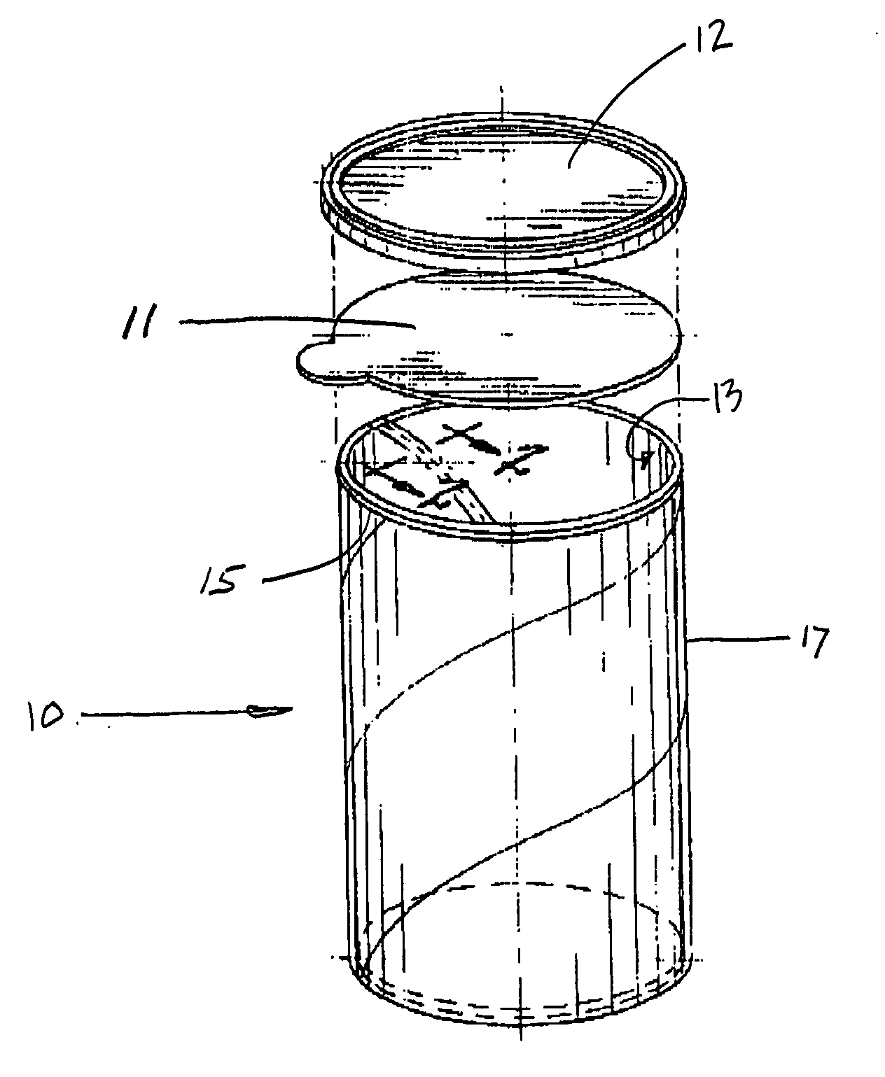
[0041] With reference to FIGS. 1 and 2, a composite container 10 is shown having an unsupported liner in accordance with the present invention. Although illustrated as having a circular cross-section, the tubular container 10 may have any cross-section shape that can be formed by wrapping the tube around an appropriately shaped mandrel. For example, the tube can be formed in a rectangular shape with rounded corners. The embodiment illustrated in FIG. 1 is particularly advantageous for packaging potato crisps ...


PUM

PropertyMeasurementUnit
polymericaaaaaaaaaa
densityaaaaaaaaaa
shapeaaaaaaaaaa

Abstract

The present invention includes methods and apparatus for making a tubular composite container having paperboard body plies and an unsupported polymer film liner adhered thereto. The polymer film liner is comprised of, in order, a first sealant layer, a second adhesive layer, a third polyamide layer, a fourth layer comprising an ethylene / vinyl alcohol copolymer, a fifth polyamide layer, a sixth adhesive layer, a seventh high density polyethylene layer and an eighth high density polyethylene layer. The resulting liner and the paperboard body plies are wound about the tube forming mandrel and adhered together so as to produce a lined tubular composite container.

Description

FIELD OF THE INVENTION [0001] The present invention relates to method and apparatus for making tubular composite containers and, more particularly, to methods and apparatus for making such containers by wrapping a multilayer polymer liner and at least one paperboard strip about an axis and adhering the various strips together. BACKGROUND OF THE INVENTION [0002] Food and drink products and other perishable items are often packaged in tubular composite containers that are sealed at both ends. These tubular containers typically include at least one structural body ply formed by wrapping a continuous strip of paperboard or other equivalent material around a mandrel of a desired shape to create a tubular structure. The body ply may be spirally wound around the mandrel or convolutely wrapped around the mandrel. In the case of spiral winding, at the downstream end of the mandrel, the tube is cut into discrete lengths and is then fitted with end closures to form the container. [0003] Exposu...

Claims


Application Information

Patent Timeline
Patent Type & Authority Applications(United States)
IPC IPC(8): B32B1/08B32B27/08
CPCB32B1/08Y10T428/1352B32B27/08B32B7/12B32B27/32B32B2323/043B32B2377/00
Inventor DRUMMOND, MICHAEL T.
Owner SONOCO DEV INC
Learn More