Component ultrasound transducer

Inactive Publication Date: 2005-07-14
LIPOSONIX
View PDF60 Cites 297 Cited by
  • Summary
  • Abstract
  • Description
  • Claims
  • Application Information

AI Technical Summary

Benefits of technology

[0023] It is still further an objective of the present invention to provide for a transducer that wi

Problems solved by technology

The procedure caused bleeding, bruising, trauma, and blood loss, restricting the amount of fat removal possible.
However the procedure still removes a significant amount of structural tissue, blood and nerve endings.
This vibration disrupts the near volume fat cells and essentially liquefies them for easy removal.
Current methods for using High Intensity Focused Ultrasound (HIFU) to form lesions in biologic tissues via cavitation effects suffer from a variety of practical limitations.
A physically large transducer practically limits clinical applications for several reasons.
Larger transducers are more difficult to keep properly coupled due to natural contours of tissue.
Larger transducers are more difficult to position so that the entire aperture is clear of intervening media such as bone or gas pockets that may degrade or destroy the ability to focus properly.
Furthermore, large transducers with very shallow focal depths are difficult, if not impossible to manufacture and apply properly.
Even if this ratio can be physically decreased, acoustic coupling becomes problematic due to critical angle effects.
A standoff can be used to physically move the transducer away from the target tissue while maintaining coupling, but this has drawbacks in terms of increased intensity

Method used


Image

  • Component ultrasound transducer
  • Component ultrasound transducer
  • Component ultrasound transducer

Examples


first embodiment

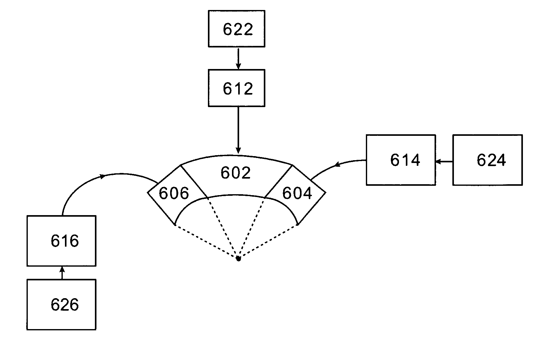
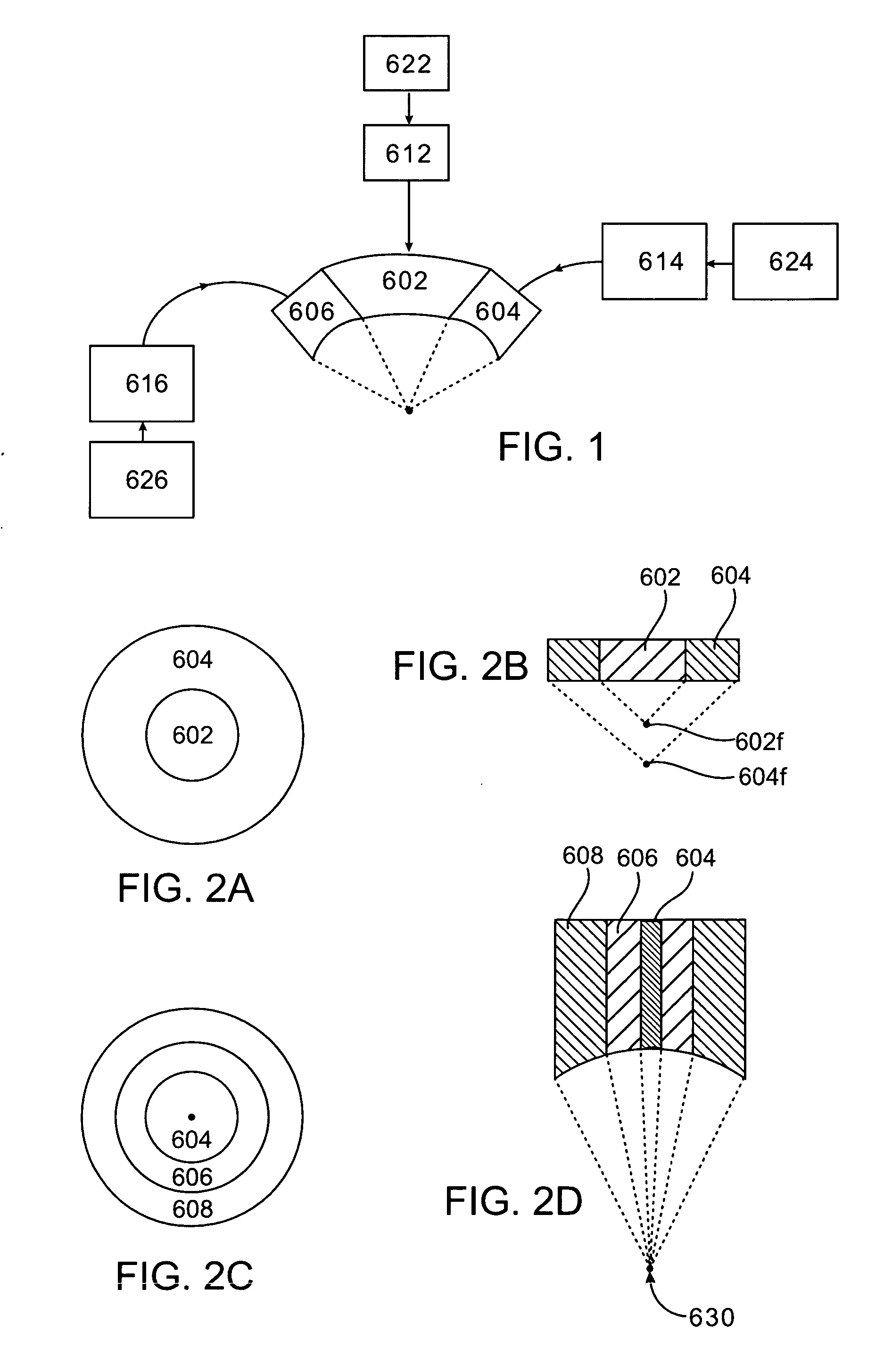
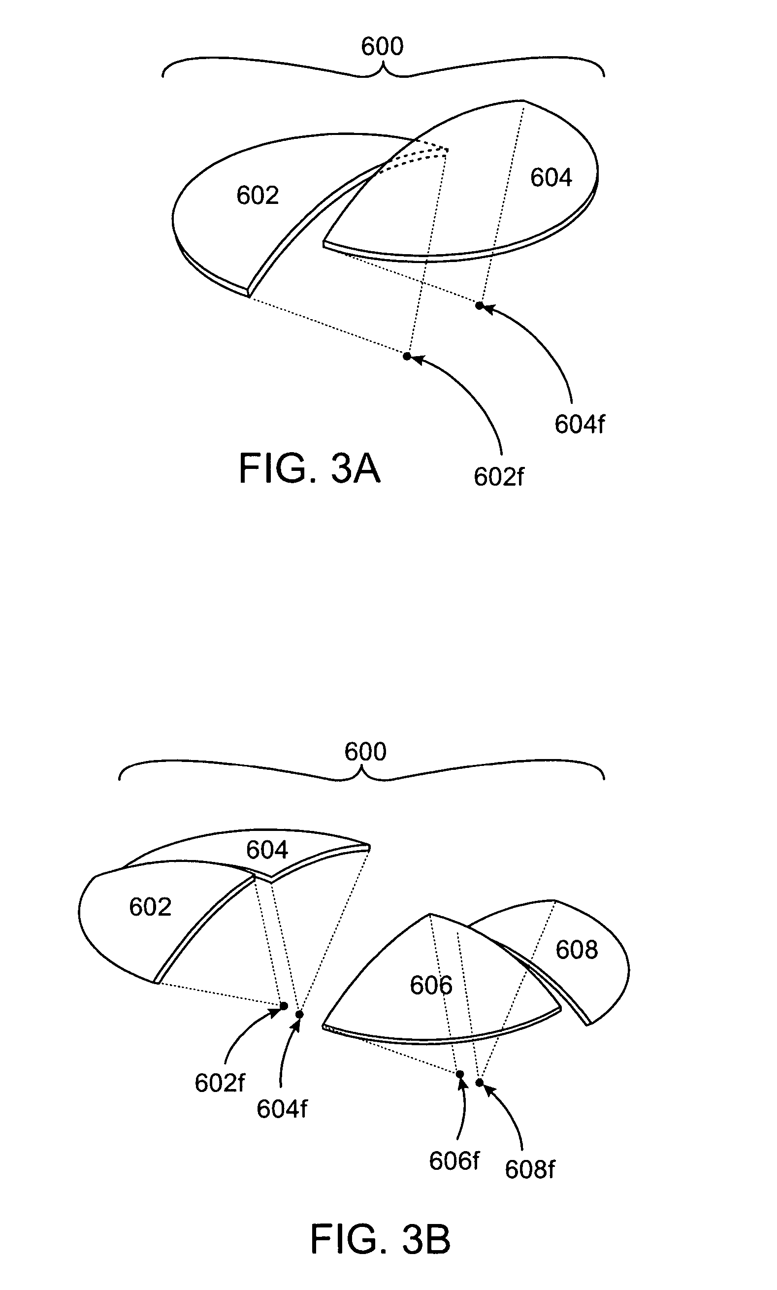
[0035] In the present invention there is an ultrasound transducer split into two or more equal size sections wherein each section has a discrete focal point. The transducer may be a hemispherical design or a flat annular array. The transducer is split into two halves or four quarters. Depending on the amount of energy that needs to be focused into the target area, the number of individual elements can be reduced and the number of partitions the transducer is split into can be increased. This with a fixed number of elements in a single transducer, the transducer can be split into as many partitions as needed or desired. Each partition then is shaped or steered to have a discrete focal zone different from each other section. The focal zones can be stacked on top of each other along the axis of the transducer, or distributed in a three dimensional volume in space before the transducer. In this way the energy from the transducer can be focused into several points at the same time.

[0036]...

second embodiment

[0038] In the present invention there is a transducer assembly having a first focused ultrasound transducer operating at a first frequency and a second transducer operation at a second frequency. During use the first transducer emits focused ultrasound energy and produces cavitation within a focal region. Micro bubbles form in the adipose tissue in response to the first transducer, and the frequency of ultrasound generated. The second transducer operates at a lower frequency and is broadcast into the patient's tissue either in focused manner or unfocused. If focused the second transducer has a focal region that overlaps the focal region of the first transducer. The focal region of the second transducer may be larger than the focal region of the first transducer so as to provide a certain safety margin for the overlapping volume of the first transducer. The frequency of the second transducer is designed to cause the collapse of the bubbles produced by the first transducer. In this wa...


PUM


Abstract

An ultrasound transducer having multiple focal zones is described. In one embodiment there is an ultrasound transducer manufactured as a single piece but having two or more focal zones. In a second embodiment there is a transducer assembly combining a high frequency and low frequency transducer. In a third embodiment there is an interchangeable assembly allowing for different ultrasound transducers to be used based on procedural needs. Variations of each embodiment are also disclosed.

Description

CROSS-REFERENCES TO RELATED APPLICATIONS [0001] This application claims the benefit of provisional application No. 60 / 534,034 (Attorney Docket No. 021356-001300US), filed on Dec. 30, 2003, the full disclosure of which is incorporated herein by reference. [0002] The subject matter of the present application is related to that of the following applications: Ser. No. 10 / 750,370, entitled “Medical Device Inline Degasser” (Attorney Docket No. 02356-000500US); Ser. No. 10 / 751,344, entitled “Articulating Arm for Medical Procedures” (Attorney Docket No. 02356-000600US); Ser. No. 10 / 750,369, entitled “Disposable Transducer Seal” (Attorney Docket No. 02356-000700US); 60 / 533,528, entitled “Position Tracking Device” (Attorney Docket No. 021356-000900US); 60 / 533,988, entitled “Method for Planning and Performing Ultrasound Therapy” (Attorney Docket No. 021356-001000US); 60 / 534,036, entitled “Ultrasound Therapy with Hood Movement Control” (Attorney Docket No. 021356-00100US); and 60 / 533,958, entit...

Claims


Application Information

Patent Timeline
IPC IPC(8): A61B8/00A61B8/14A61B17/22B06B1/06
CPCA61B8/00B06B1/0637A61B8/4438A61B8/4483A61B2017/22008A61B2017/22028A61M2202/08A61N7/02A61N2007/0008A61N2007/0039A61N2007/0065A61N2007/0073A61N2007/0078A61N2007/027B06B1/0625A61B8/4411A61H1/02
Inventor QUISTGAARD, JENS U.
Owner LIPOSONIX
Why Eureka
Try Eureka