
Plasma display panel

Inactive Publication Date: 2005-07-21
PANASONIC CORP
View PDF9 Cites 6 Cited by
  • Summary
  • Abstract
  • Description
  • Claims
  • Application Information

AI Technical Summary

Benefits of technology

[0013] With this structure, in a priming discharge in the vertical direction between the first substrate and the second substrate, thinning a portion of the dielectric layer that corresponds to the second discharge space, which is the priming discharge space, increases the capacitance of the dielectric layer so as to raise the value of an effective voltage to be applied to discharge gaps, thereby making it possible to stimulate generation of a priming discharge. As a result, increasing the operating margin of the priming discharge and reducing a discharge voltage can form a stable priming discharge while reducing influence on the surroundings, such as crosstalk, thereby achieving a PDP with excellent address properties so as to be compatible with high definition.

Problems solved by technology

In this type of PDP, a large delay in discharge occurs during the address period, thereby making the address operation unstable, or completion of the address operation requires a long address time, thereby spending too much time for the address period.
However, in these conventional PDPs, when the number of lines is increased as a result of achieved higher definition, more time must be spent for the address time and less time must be spent for the sustain period, thereby making it difficult to secure the brightness when higher definition is achieved.
Furthermore, when the partial pressure of xenon (Xe) is increased to achieve higher brightness and higher efficiency, a discharge initiation voltage rises so as to increase a discharge delay, thereby deteriorating address properties.
In spite of this demand, in conventional PDPs performing a priming discharge in the front plate surface, a discharge delay during the addressing cannot be reduced sufficiently; the operating margin of an auxiliary discharge is small; and a false discharge is induced to make the operation unstable.
Moreover, since the auxiliary discharge is performed in the front plate surface, more priming particles than necessary for priming are applied to an adjacent discharge cell, thereby causing crosstalk.

Method used


Image

  • Plasma display panel
  • Plasma display panel
  • Plasma display panel

Examples


first exemplary embodiment

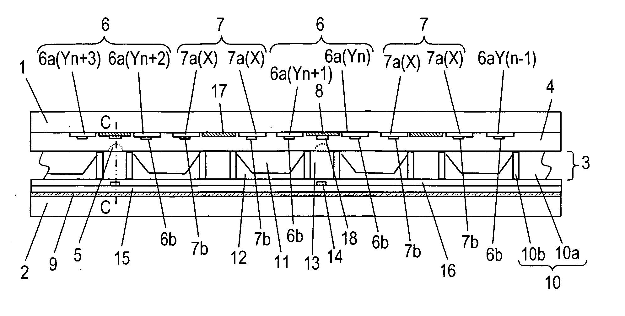
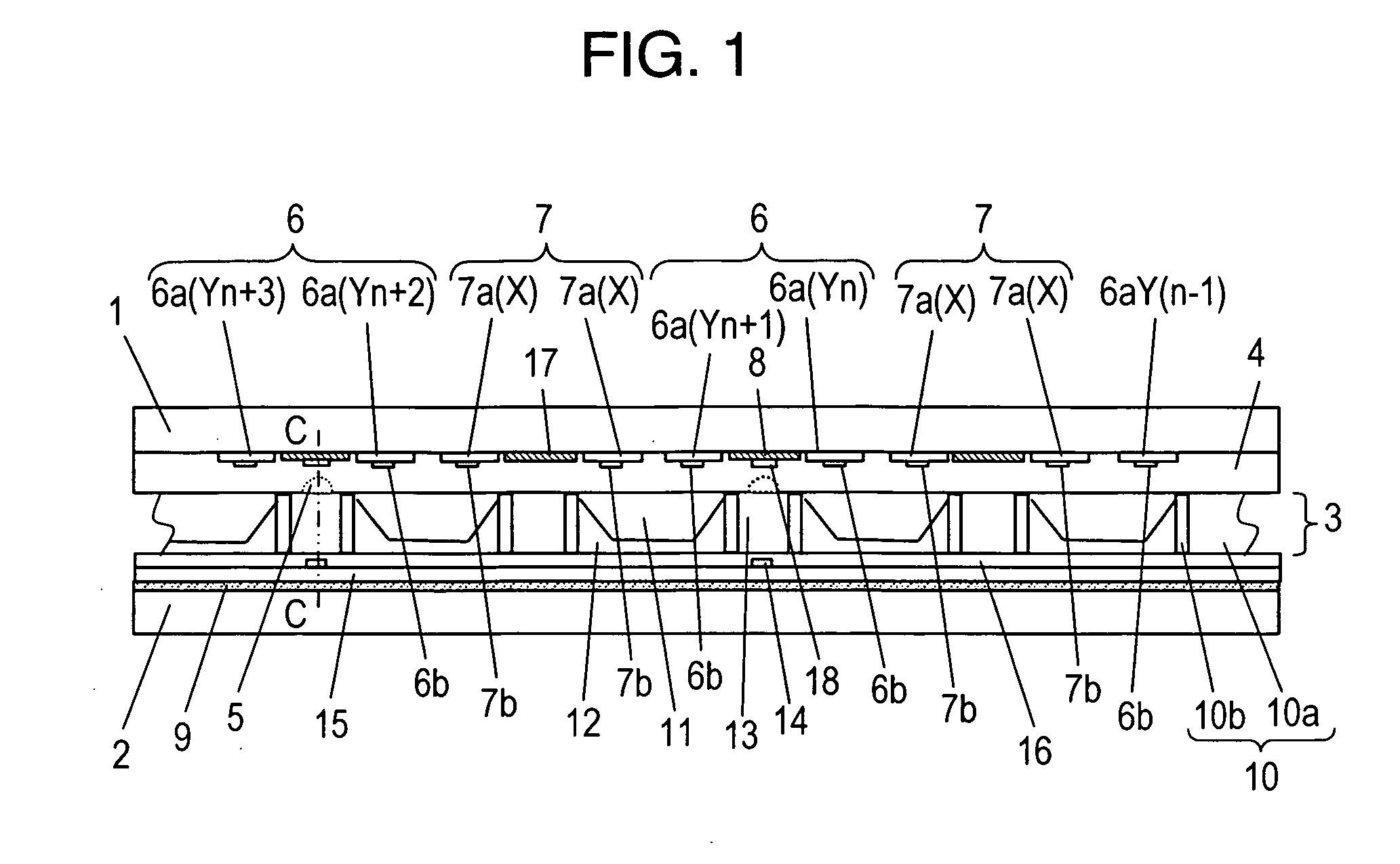
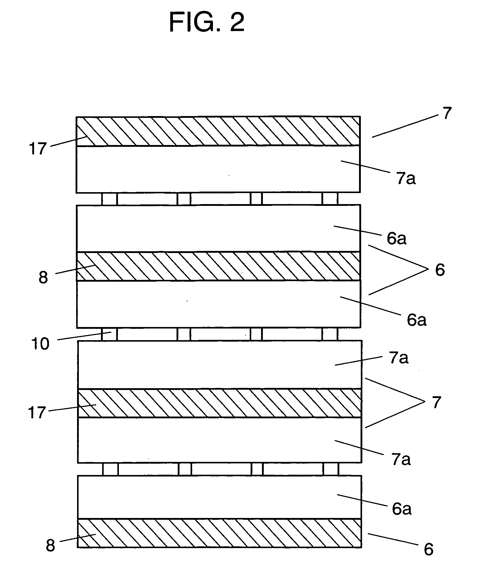
[0021]FIG. 1 is a cross sectional view of a PDP according to a first embodiment of the present invention, FIG. 2 is a schematic plan view showing an electrode arrangement on a front substrate side, which is a first substrate side, FIG. 3 is a schematic perspective view showing a back substrate side, which is a second substrate side and FIG. 4 is a plan view thereof.

[0022] As shown in FIG. 1, front substrate 1 which is a first substrate made of glass, and back substrate 2 which is a second substrate made of glass are disposed to face each other with discharge space 3 therebetween, and discharge space 3 is sealed with neon (Ne), xenon (Xe) and the like as gasses for irradiating ultraviolet rays by discharge. On front substrate 1, a group of belt-shaped electrodes consisting of pairs of scan electrodes 6 as first electrodes and sustain electrodes 7 as second electrodes are disposed in parallel with each other in such a manner as to be covered with dielectric layer 4 and protective lay...

second exemplary embodiment

[0030]FIG. 6 is a schematic perspective view showing a back substrate side of a PDP according to a second embodiment of the present invention. In the present embodiment, gap parts 13 for forming priming cells are shaped into a parallel cross pattern with longitudinal rib parts 10a and lateral rib parts 10b.

[0031] In a case that gap parts 13 are formed continuously with lateral rib parts 10b only as described in the first embodiment, in intersections between longitudinal rib parts 10a and lateral rib parts 10b, distortion may appear on lateral rib parts 10b by heat shrinkage of longitudinal rib parts 10a in particular so as to decrease plane precision in barrier ribs 10, thereby adversely affecting crosstalk and the like. For this, it is effective to provide longitudinal rib pars 10a also to gap parts 13 as shown in FIG. 6.

[0032] On the other hand, when longitudinal rib parts 10a and lateral rib parts 10b are shaped into a parallel cross pattern with the same height, a priming disc...


PUM


Abstract

A plasma display panel has address properties stabilized. A priming discharge is performed between auxiliary electrodes (18), which are formed on a front substrate (1) and coupled with scan electrodes (6), and priming electrodes (14) formed on a back substrate (2). And on the front substrate (1), a dielectric layer (4) is made thinner in regions corresponding to priming cells (gap parts 13) than in regions corresponding to cell parts (11). As a result, the priming discharge has a wider margin, and a supply of priming particles to the discharge cells is stabilized, whereby a discharge delay during the addressing is reduced, and the address properties are stabilized.

Description

TECHNICAL FIELD [0001] The present invention relates to plasma display panels used for wall-hung TVs and large-size monitors. BACKGROUND ART [0002] An AC surface discharge type plasma display panel (hereinafter referred to as PDP), which is a typical AC type PDP, is formed of a front plate made of a glass substrate having scan electrodes and sustain electrodes provided thereon for a surface discharge, and a back plate made of a glass substrate having data electrodes provided thereon. The front plate and the back plate are disposed to face each other in parallel in such a manner that the electrodes on both plates form a matrix, and that a discharge space is formed between the plates. And the outer part of the plates thus combined is sealed with a sealing member such as a glass frit. Between the substrates, discharge cells partitioned by barrier ribs are formed, and phosphor layers are provided in the cell spaces formed by the barrier ribs. In a PDP with this structure, ultraviolet ra...

Claims


Application Information

Patent Timeline
IPC IPC(8): H01J11/14H01J11/22H01J11/24H01J11/28H01J11/34H01J11/36H01J11/38
CPCH01J11/38H01J11/12H01J11/22H01J11/36
Inventor TACHIBANA, HIROYUKIFUJITANI, MORIONOGUCHI, YASUYUKISHIRAI, TATSUYA
Owner PANASONIC CORP
Learn More