Organic electroluminescent element
- Summary
- Abstract
- Description
- Claims
- Application Information
AI Technical Summary
Benefits of technology
Problems solved by technology
Method used
Image
Examples
example 1
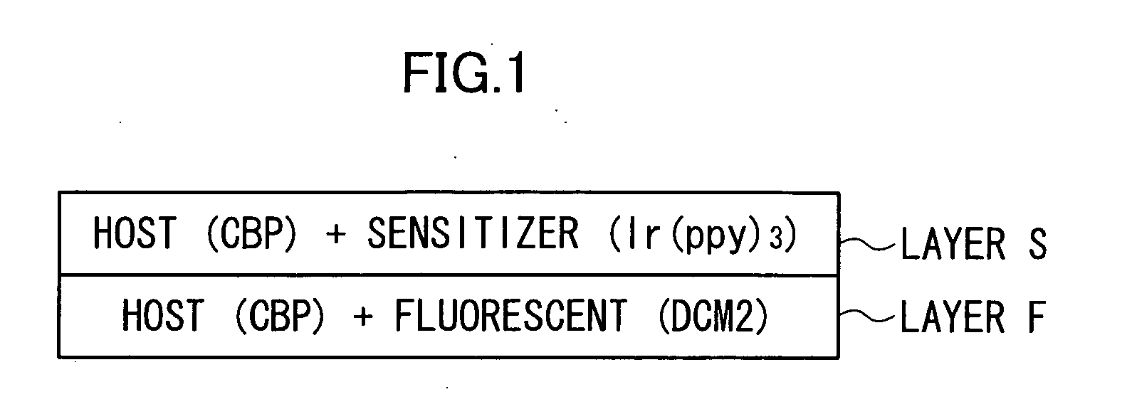
[0077] An indium tin oxide (ITO) substrate was washed and put into a vapor deposition device, and N,N′-diphenyl-N,N′-di(m-tolyl)benzidine (TPD) was vapor-deposited thereon to form a first layer having a thickness of 50 nm. The compound A and rubrene were vapor-deposited on the first layer at a ratio of 99:1 to form a secondary layer having a thickness of 1 nm. Next, a compound B having a structure shown below and Ir(ppy)3 were vapor-deposited on the secondary layer at a ratio of 17:1 to form a tertiary layer having a thickness of 1 nm. This process for forming the secondary and tertiary layers was repeated 18 times to form a thin film having a total thickness of 36 nm. During this process, a crucible on which the compound A and rubrene were placed and a crucible on which the compound B and Ir(ppy)3 were placed were constantly heated at a temperature at which vapor deposition could be carried out, and the vapor deposition was carried out repeatedly by switching a shutter provided in ...
example 2
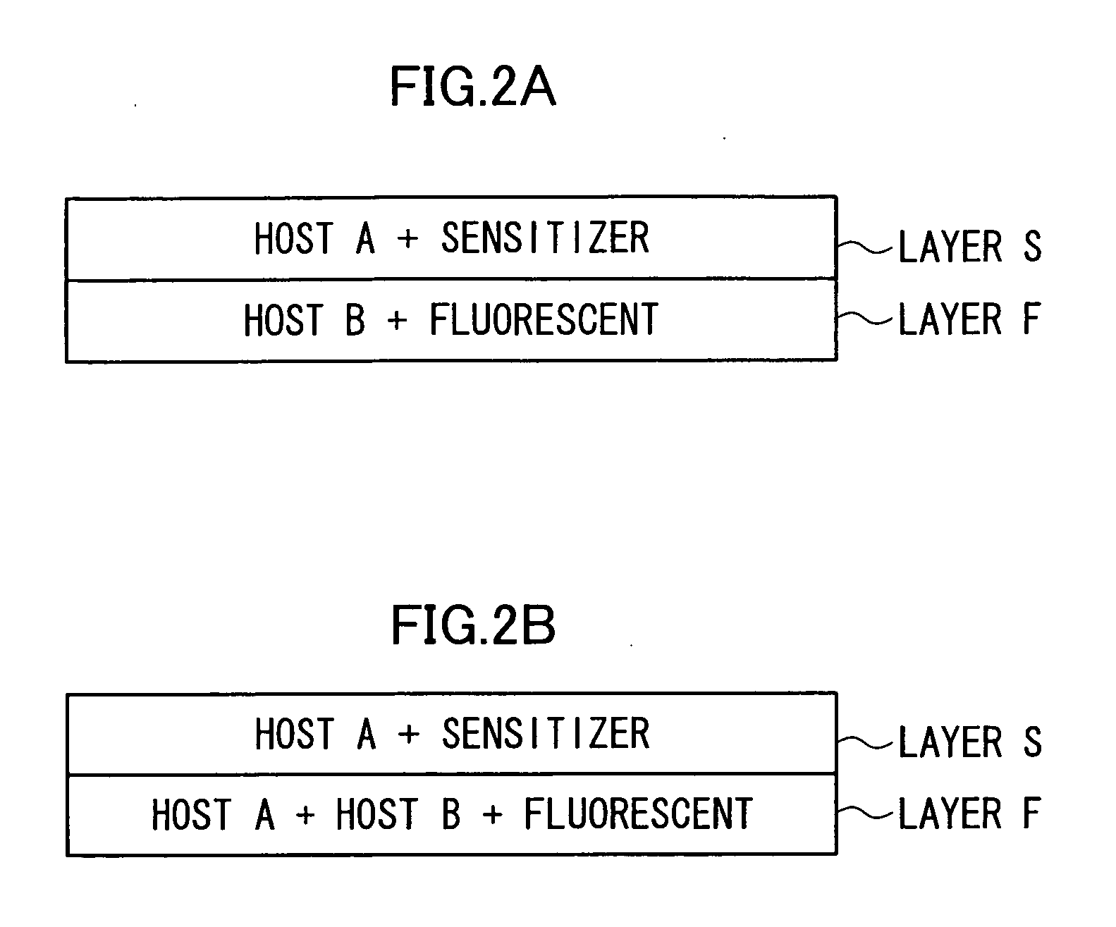
[0081] An organic EL element of Example 2 containing two host materials (compounds A and C) was prepared in the same manner as in Example 1, except that the compound C was used instead of the compound B. The organic EL element was evaluated in the same manner as in Comparative Example 1. As a result, yellow luminescence having λmax of 565 nm and chromaticity (x, y) of (0.44, 0.53) was obtained, and the external quantum efficiency at 200 cd / m2 was 17.6%.
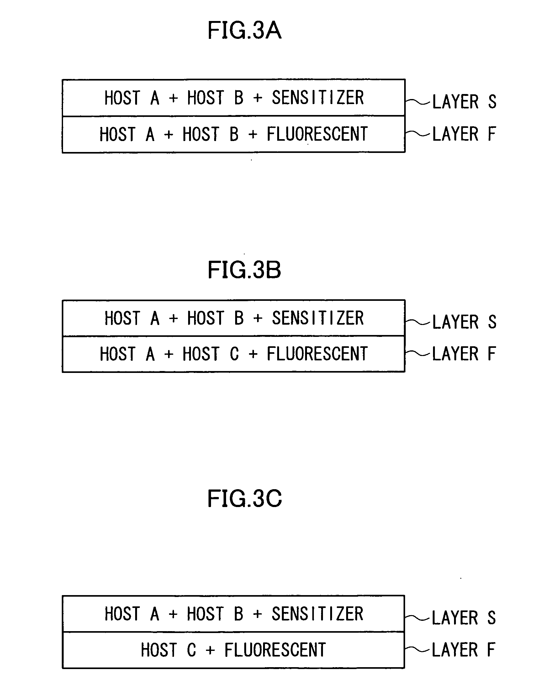
[0082] As in the luminescent layer of the luminescent element of Example 1, the luminescent layer of the element of Example 2 had layers each containing a fluorescent and a host material and layers each containing a sensitizer and another host material.
example 3
[0083] An organic EL element of Example 3 containing two host materials (compounds B and D) was prepared in the same manner as in Example 1, except that the compound B was used instead of the compound A and that the compound D was used instead of the compound B. The organic EL element was evaluated in the same manner as in Comparative Example 1. As a result, yellow luminescence having λmax of 563 nm and chromaticity (x, y) of (0.46, 0.52) was obtained, and the external quantum efficiency at 200 cd / m2 was 13.7%.
[0084] As in the luminescent layer of the luminescent element of Example 1, the luminescent layer of the element of Example 3 had layers each containing a fluorescent and a host material and layers each containing a sensitizer and another host material.
PUM
| Property | Measurement | Unit |
|---|---|---|
| Electroluminescence | aaaaa | aaaaa |
| Fluorescence | aaaaa | aaaaa |
| Luminous intensity | aaaaa | aaaaa |
Abstract
Description
Claims
Application Information
 - R&D
- Intellectual Property
- Life Sciences
- Materials
- Tech Scout
- Unparalleled Data Quality
- Higher Quality Content
- 60% Fewer Hallucinations
Browse by: Latest US Patents, China's latest patents, Technical Efficacy Thesaurus, Application Domain, Technology Topic, Popular Technical Reports.
© 2025 PatSnap. All rights reserved.Legal|Privacy policy|Modern Slavery Act Transparency Statement|Sitemap|About US| Contact US: help@patsnap.com


