Refrigeration source for a cryoablation catheter

a cryoablation catheter and refrigeration source technology, which is applied in the direction of catheters, domestic cooling devices, lighting and heating devices, etc., can solve the problems of radiofrequency energy not being able to safely produce circumferential lesions without serious complications, matrix collapse, radiofrequency energy being known to damage the lining of the heart, etc., and achieves a small flow diameter. , the effect of significantly reducing the cooling power

Inactive Publication Date: 2005-07-21
WALTON JAY RODNEY +4
View PDF0 Cites 21 Cited by
  • Summary
  • Abstract
  • Description
  • Claims
  • Application Information

AI Technical Summary

Benefits of technology

[0010] In a cryosurgical system, contaminants such as oil, moisture, and other impurities are often deposited in the impedance tubing or other restriction through which the refrigerant is pumped. In the impedanc

Problems solved by technology

Radiofrequency energy, however, is not amenable to safely producing circumferential lesions without the potential for serious complications.
Specifically, while ablating the myocardial cells, heating energy also alters the extracellular matrix proteins, causing the matrix to collapse.
Moreover, radiofrequency energy is known to

Method used


Image

  • Refrigeration source for a cryoablation catheter
  • Refrigeration source for a cryoablation catheter
  • Refrigeration source for a cryoablation catheter

Examples


first embodiment

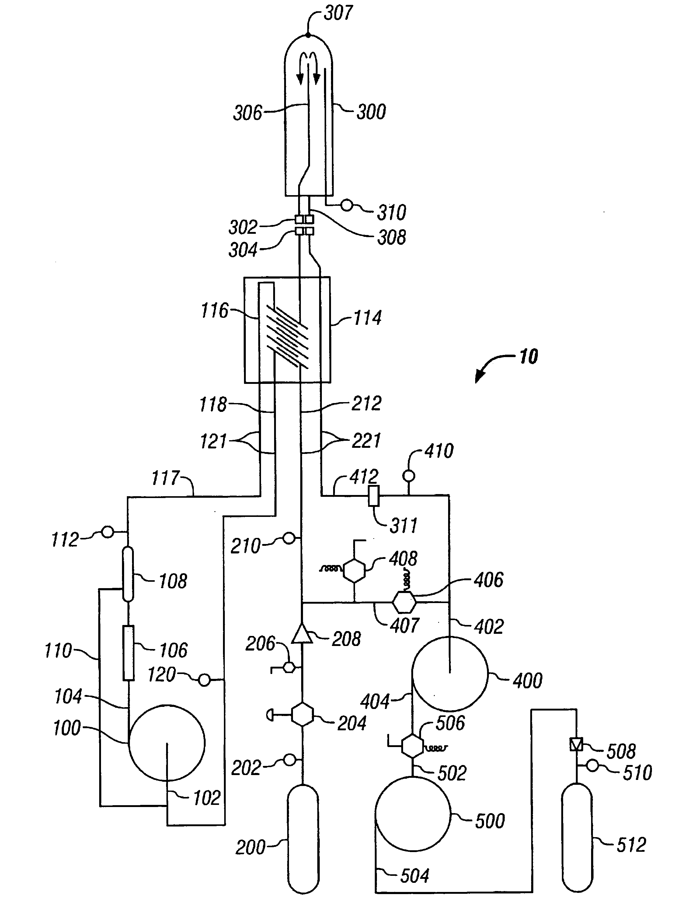
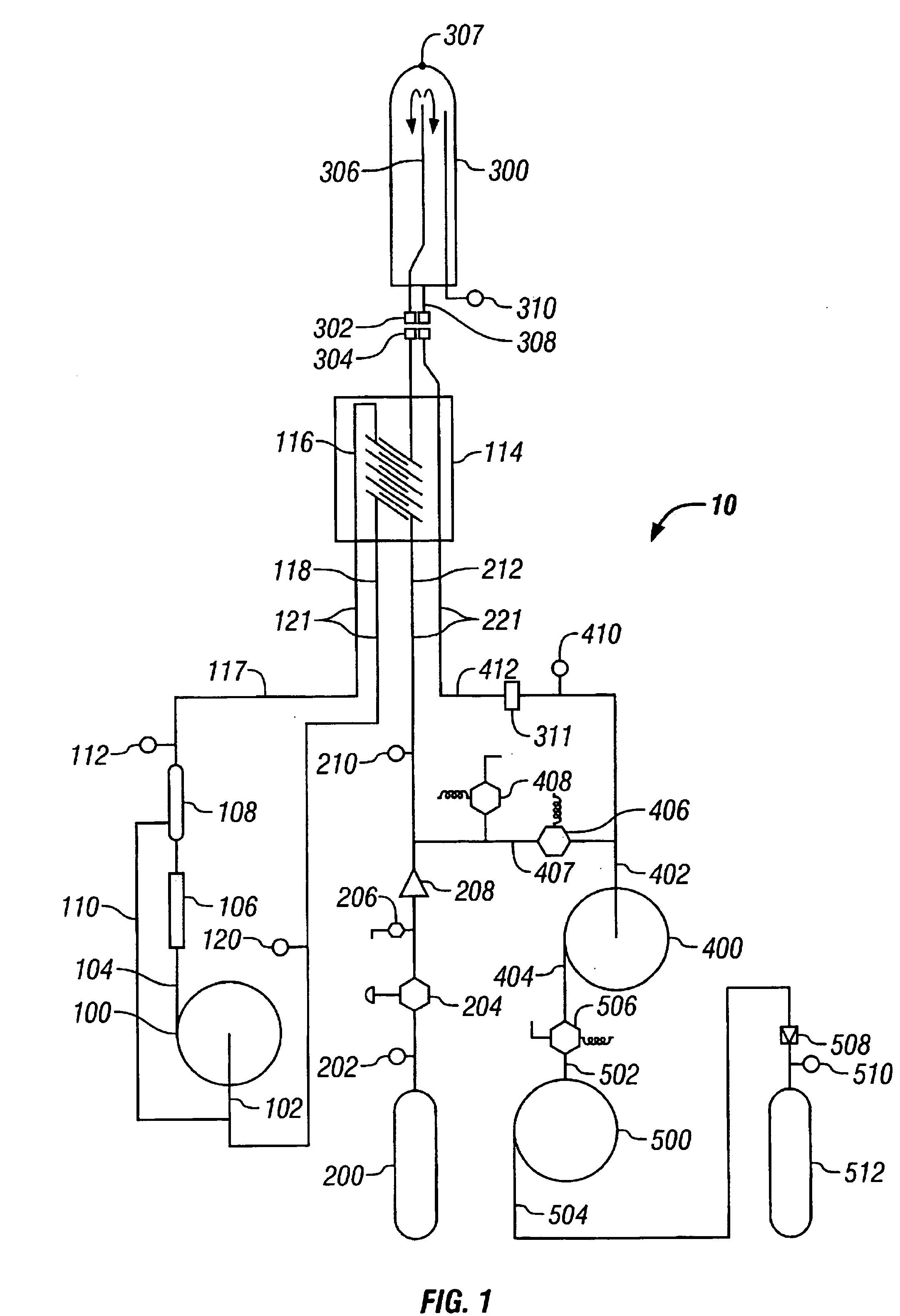
[0030]FIG. 1 is a schematic of the apparatus of the present invention, using a pressure bottle as the primary refrigerant source;

second embodiment

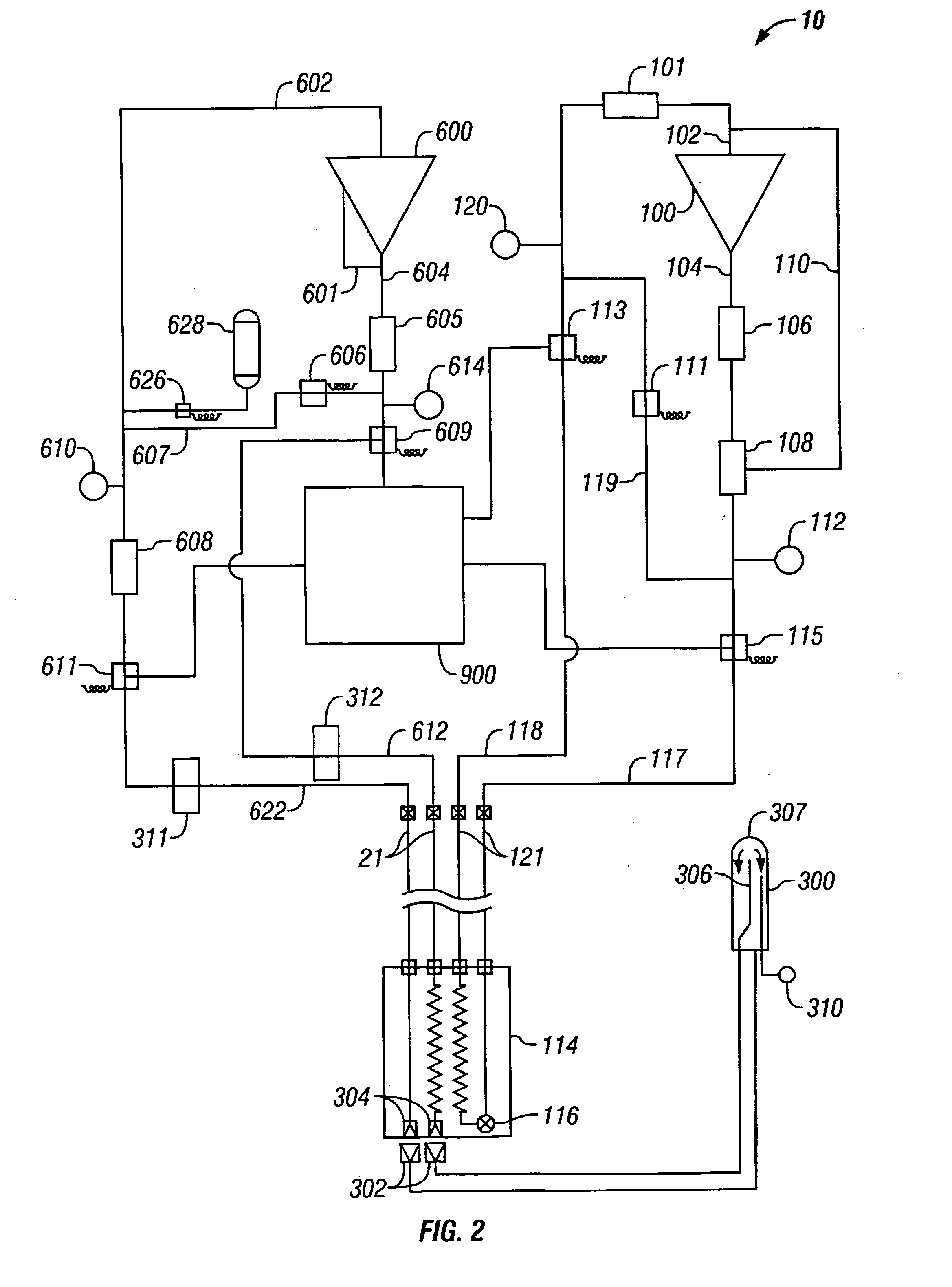
[0031]FIG. 2 is a schematic of the apparatus of the present invention, using a compressor as the primary refrigerant source;

third embodiment

[0032]FIG. 3 is a schematic of the apparatus of the present invention, using two compressors connected in series as the primary refrigerant source;

[0033]FIG. 4 is a schematic of a first embodiment of a control system apparatus according to the present invention, for use with the apparatus shown in FIG. 1;

[0034]FIG. 5 is a schematic of a second embodiment of a control system apparatus according to the present invention, for use with the apparatus shown in FIG. 2 or 3;

[0035]FIG. 6 is a schematic of a parameter display for use with the control equipment of the present invention; and

[0036]FIG. 7 is a flow diagram showing one control sequence for use with the control apparatus of the present invention.

[0037]FIG. 8 is a perspective view of the system of the present invention;

[0038]FIG. 9 is a cross-sectional view of the catheter of the present invention as seen along the line 2-2 in FIG. 8;

[0039]FIG. 10 is a schematic view of the computer and its interaction with system components a...


PUM


Abstract

An apparatus and method for automatic operation of a refrigeration system to provide refrigeration power to a catheter for tissue ablation or mapping. The primary refrigeration system can be open loop or closed loop, and a precool loop will typically be closed loop. Equipment and procedures are disclosed for bringing the system to the desired operational state, for controlling the operation by controlling refrigerant flow rate, for performing safety checks, and for achieving safe shutdown. The catheter-based system for performing a cryoablation procedure uses a precooler to lower the temperature of a fluid refrigerant to a sub-cool temperature (−40° C.) at a working pressure (400 psi). The sub-cooled fluid is then introduced into a supply line of the catheter. Upon outflow of the primary fluid from the supply line, and into a tip section of the catheter, the fluid refrigerant boils at an outflow pressure of approximately one atmosphere, at a temperature of about −88° C. In operation, the working pressure is computer controlled to obtain an appropriate outflow pressure for the coldest possible temperature in the tip section.

Description

[0001] This application is continuation of application Ser. No. 10 / 243,997, which is currently pending and which is a continuation-in-part of application Ser. No. 09 / 635,108 filed Aug. 9, 2000, now U.S. Pat. No. 6,471,694. The contents of application Ser. Nos. 10 / 243,997 and 09 / 635,108 are incorporated herein by reference.FIELD OF THE INVENTION [0002] The present invention pertains generally to systems and methods for implementing cryoablation procedures. More particularly, the present invention pertains to systems and methods that precool a primary fluid to a sub-cooled, fully saturated liquid state, for use in a cryoablation procedure. The present invention is particularly, but not exclusively, useful as a system and method for cooling the distal tip of a cryoablation catheter during cardiac cryoablation therapy to cure heart arrhythmias. The present invention also relates to the field of methods and apparatus used to generate and control the delivery of cryosurgical refrigeration...

Claims


Application Information

Patent Timeline
IPC IPC(8): A61B18/02A61F7/00A61B17/00A61F7/10A61F7/12A61M25/00F25B9/02
CPCA61B18/02A61B2017/00199A61B2018/0212A61B2018/0262F25D2400/36F25B9/02F25B2700/13F25D3/10A61B2018/0268F25D16/00
Inventor WALTON, JAY RODNEYZHENG, LIZHONGKETCHUM, JOHN W.WALLACE, MARK S.HOWARD, STEVEN J.
Owner WALTON JAY RODNEY
Why Eureka
Try Eureka