Method and apparatus for FAIMS with a laser-based ionization source

a laser-based ionization source and laser-based technology, applied in the field of high-field asymmetric waveform ion mobility spectrometry, can solve the problems of inability to operate the separation technology in a continuous mode using existing chromatographic and electrophoretic techniques, the separation method requires relatively long time periods to achieve the separation, and the mass spectrometer spends significant periods of time waiting. to achieve the effect of rapid screening of samples

Inactive Publication Date: 2005-07-28
THERMO FINNIGAN +1
View PDF8 Cites 20 Cited by
  • Summary
  • Abstract
  • Description
  • Claims
  • Application Information

AI Technical Summary

Benefits of technology

[0014] It is also an object of at least some of the embodiments of the instant invention to provide a method and an

Problems solved by technology

Because of the time that it takes for the components to migrate, chromatographic and electrophoretic methods require relatively long time periods to accomplish the separation, on the order of several minutes, whereas analysis by mass spectrometric methods provides data almost immediately.
In practice, therefore, the mass spectrometer spends significant periods of time waiting for the arrival of transient signals.
This is inefficient since the separation technology is very much less expensive than the MS instrumentation.
As will be obvious to one of ordinary skill in the art, operation of the separation technology in a continuous mode is impossible using existing chromatographic and electrophoretic techniques because the component of interest arrives only as a transient at the end of the separation.
This transient mode of operation limits significantly the number and types of experiments that can be conducted during the lifetime of a given transient signal.
Furthermore, if the information that is acquired during the transient is insufficient, a new sample must be injected and a delay is encountered during which the components are being separated.
However, tandem MS requires considerable method development time and the operator must have expertise to operate

Method used


Image

  • Method and apparatus for FAIMS with a laser-based ionization source
  • Method and apparatus for FAIMS with a laser-based ionization source
  • Method and apparatus for FAIMS with a laser-based ionization source

Examples


Embodiment Construction

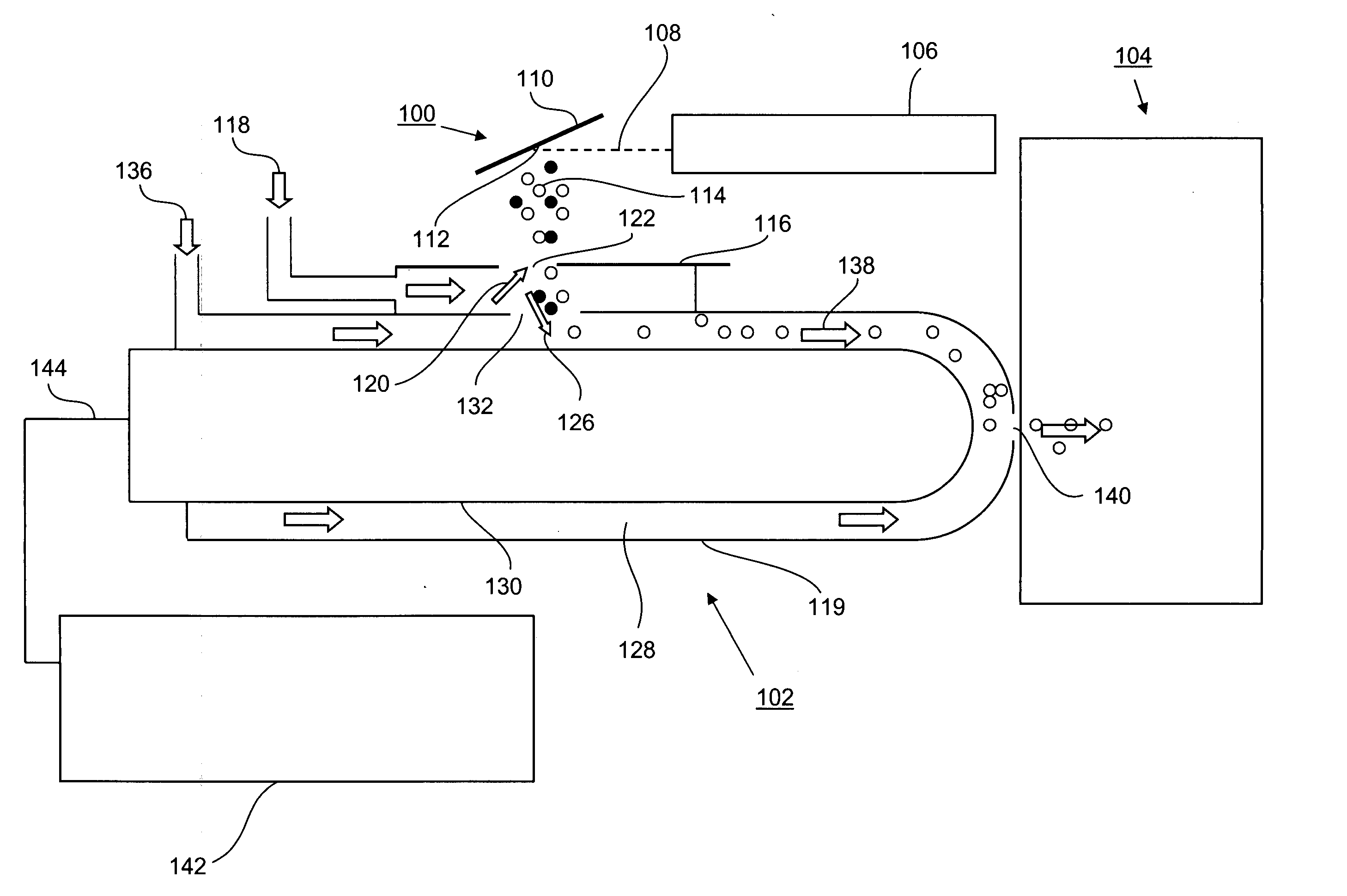
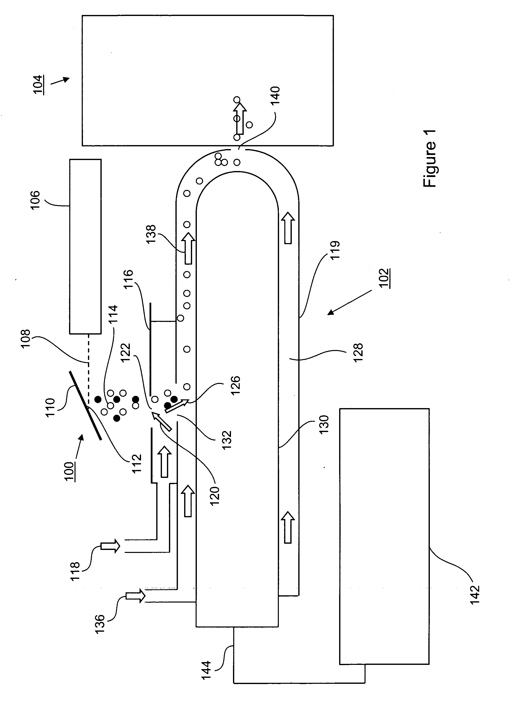
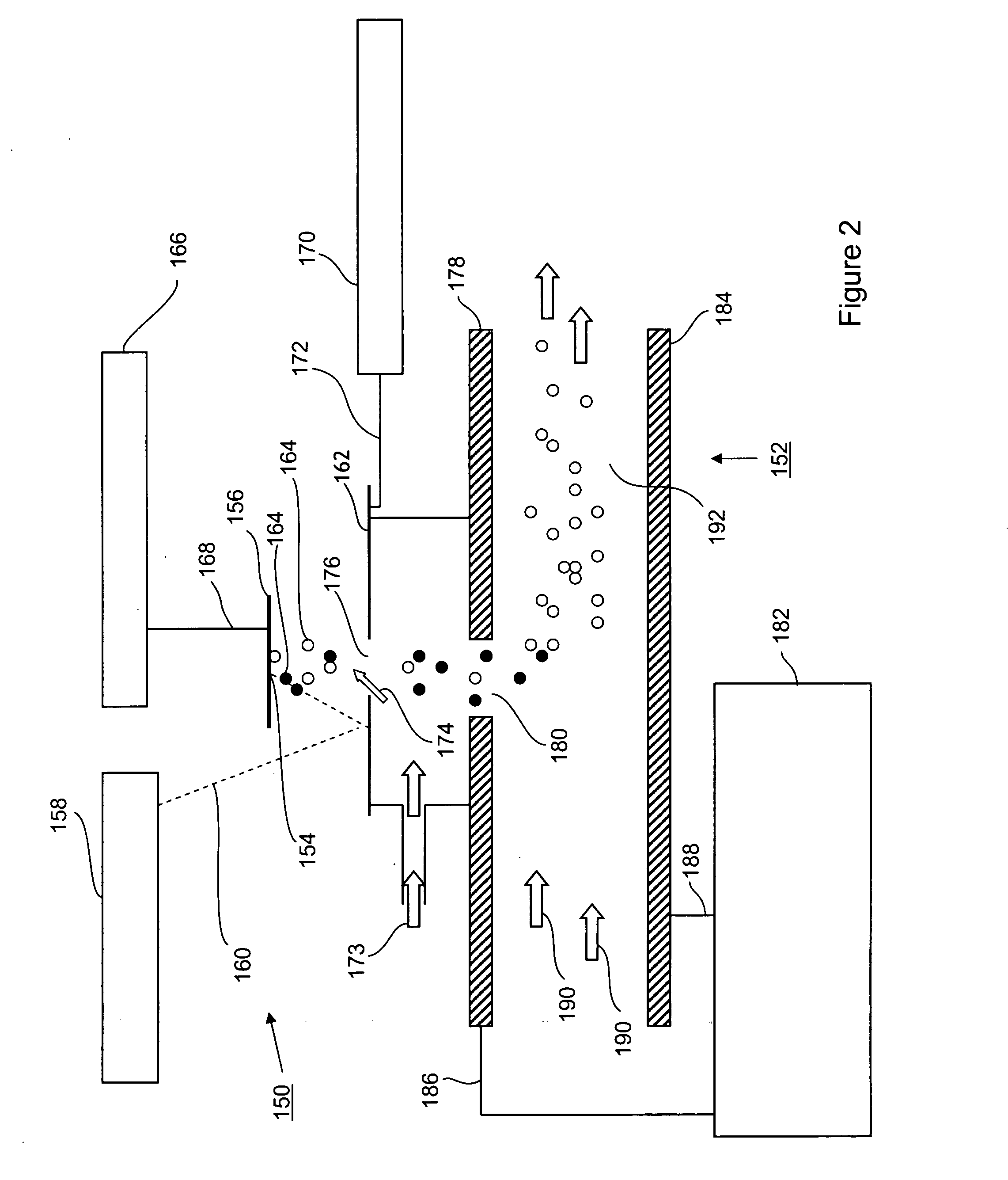
[0034] Exemplary embodiments of the invention will now be described in conjunction with the accompanying drawings. The following description is presented to enable a person skilled in the art to make and use the invention, and is provided in the context of a particular application and its requirements. Various modifications to the disclosed embodiments will be readily apparent to those skilled in the art, and the general principles defined herein may be applied to other embodiments and applications without departing from the spirit and the scope of the invention. Thus, the present invention is not intended to be limited to the embodiments disclosed, but is to be accorded the widest scope consistent with the principles and features disclosed herein.

[0035] Throughout the detailed description, reference is made primarily to atmospheric pressure MALDI, although it is to be understood that other atmospheric pressure ionization techniques, particularly laser based techniques such as atmo...


PUM


Abstract

A method of separating ions comprises applying a spot of a sample material to a target plate. The target plate is mounted in fluid communication with an ion inlet orifice of a FAIMS analyzer region and externally to the FAIMS analyzer region. Using a laser light source that is disposed external to the FAIMS analyzer region, the target plate is irradiated with light of a predetermined wavelength, the light of a predetermined wavelength being selected to affect the sample material applied to the target plate so as to produce ions of the sample material. The ions of the sample material are directed along an ion flow path between the target plate and FAIMS analyzer region, via the ion inlet orifice. A flow of a gas is directed counter-current to the ion flow path and passing through the target plate. The flow of gas through the target plate assists in desolvation of ions and directs neutral molecules away from the FAIMS analyzer region.

Description

[0001] This application claims benefit from U.S. Provisional Application No. 60 / 537,881 filed Jan. 22, 2004.FIELD OF THE INVENTION [0002] The instant invention relates generally to High-Field Asymmetric Waveform Ion Mobility Spectrometry (FAIMS), and more particularly to FAIMS with a laser-based ionization source. BACKGROUND OF THE INVENTION [0003] Biochemical and pharmaceutical applications have requirements for rapid screening and detection of compounds in extremely complex mixtures. Advances in chemical analysis technology applied to these fields must achieve a high degree of specificity in separations and incorporate systems that avoid slow separations, especially those involving chromatography and electrophoresis. [0004] At present, the compounds in complex mixtures are separated and analyzed by chromatographic and electrophoretic methods combined with atmospheric pressure ionization-mass spectrometry (API-MS). In these separation techniques, a portion of a sample is introduced...

Claims


Application Information

Patent Timeline
IPC IPC(8): B01D59/44G01N27/64H01J49/28H01J49/40H01J49/42
CPCG01N27/624H01J49/0418H01J49/0413
Inventor GUEVREMONT, ROGERDWORSCHAK, RAGNARYOST, RICHARD A.HILTON, CHRISTOPHER KARLBELFORD, MICHAEL WILLIAM
Owner THERMO FINNIGAN
Why Eureka
Try Eureka