Dielectric motors with electrically conducting rotating drive shafts and vehicles using same

a technology of electric conducting rotating drive shaft and dielectric motor, which is applied in piezoelectric/electrostrictive/magnetostrictive devices, piezoelectric/electrostriction/magnetostriction machines, electrical apparatus, etc., can solve the problems of low radar reflectivity, engine dissipation a great deal of energy, and combustion engines that are not suitable for some vehicles, such as satellites and other spacecra

Active Publication Date: 2005-07-28
THE JOHN HOPKINS UNIV SCHOOL OF MEDICINE
View PDF5 Cites 27 Cited by
  • Summary
  • Abstract
  • Description
  • Claims
  • Application Information

AI Technical Summary

Benefits of technology

[0016] Motors are provided that enable lightweight, powered vehicles with low radar reflectivity. The motors include a support framework and a mechanical movement component moveably mounted to the support framework. An electroactive polymer device having a pair of input electrodes is configured to deform upon application of an electric potential difference across the pair of input electrodes. The electroactive polymer device is mechanically linked to the support framework and to the mechanical movement component so that deformation of the electroactive polymer device causes the movement component to move relative to the support framework.
[0018] According to another set of embodiments a rolled electroactive polymer device is used with a rotating movement component. In these embodiments the rolled electroactive polymer device has a pair of input electrodes and is configured to deform primarily parallel to a roll longitudinal axis upon application of an electric potential difference across the pair of input electrodes. The movement component is a rotating shaft. Deformation of the rolled electroactive polymer device causes the shaft to complete a revolution relative to the support framework.
[0019] According to one set of embodiments, the support framework includes a sleeve that has a sleeve longitudinal axis and a sleeve base. A rolled electroactive polymer device is disposed in the sleeve with the roll longitudinal axis aligned with the sleeve longitudinal axis. The movement component is a crankshaft mounted to the support framework so as to allow the crankshaft to rotate with respect to the support framework. A first portion of the rolled electroactive polymer device pushes against the sleeve base and a second, different portion of the rolled electroactive polymer device is mechanically connected to a crank pin of the crankshaft. Deformation of the rolled electroactive polymer device causes the crankshaft to rotate with respect to the support framework.
[0031] According to one set of embodiments, a lightweight, powered vehicle with low radar reflectivity includes a vehicle chassis, a motor, and a propeller. The vehicle chassis has low radar reflectivity for deployment in a fluid medium. The motor is mounted to the vehicle chassis, and includes a support framework, a shaft and multiple electroactive polymer devices. The support framework has low radar reflectivity. The shaft has low radar reflectivity and is rotatably mounted to the support framework. Each device has a pair of input electrodes configured to deform upon application of an electric potential difference across the pair of input electrodes. The electroactive polymer devices are mechanically linked to the support framework and to the shaft so that deformation of the electroactive polymer devices causes the shaft to rotate relative to the support framework with at least one horsepower. The propeller has low radar reflectivity, and is mechanically connected to the shaft to rotate the propeller. The fluid medium is moved relative to the vehicle chassis by rotating the propeller.

Problems solved by technology

Conventional electric motors and combustion engines are widely used in commerce but are not appropriate for all applications.
Such engines dissipate a great deal of energy as heat, require massive engine blocks to withstand the explosions, are made of metals that have high reflectivity to radar, and require oxygen that may be in short supply at high altitudes.
The oxygen requirement, alone, makes combustion engines unsuitable for some vehicles, such as satellites and other spacecraft.
These motors draw substantial current and therefore require relative heavy sources of electrical power, such as AC generators and large banks of batteries.
Compressed gas and hydraulic motors require a source of gas or hydraulic fluid and have poor energy efficiency as chemical energy is converted first to pressure and then to mechanical movement.
However, such linear motors suffer some disadvantages.
Such components add to complexity and are subject to wear and breakdown.
Such linear motors also fail to take advantage of a wide range of well established technologies to use rotating drive shafts, such as are common in the automobile and aircraft industries.
However, the motors described in Heim I and Heim II provide low power—well less than one horsepower, and therefore insufficient to move a propeller such as envisioned for some applications.
Furthermore, the described motors involve numerous joints and extensions to convert small stroke linear deformations into rotating movement; such joints and extensions add to complexity and are subject to wear and failure.
In addition, the space required for long beams to extend from the EAP to a rotating shaft increases the size and weight of the motor.
Joints and pins located at one point in the sheet are subject to large stresses and can be expected to be a point of failure, such as a source of a fissure in the sheet.

Method used


Image

  • Dielectric motors with electrically conducting rotating drive shafts and vehicles using same
  • Dielectric motors with electrically conducting rotating drive shafts and vehicles using same
  • Dielectric motors with electrically conducting rotating drive shafts and vehicles using same

Examples


Embodiment Construction

[0051] Motors and vehicle are described that employ electroactive polymer (EAP) devices. In the following description, for the purposes of explanation, numerous specific details are set forth in order to provide a thorough understanding of the present invention. It will be apparent, however, to one skilled in the art that the present invention may be practiced without these specific details. In other instances, well-known structures and devices are shown in block diagram form in order to avoid unnecessarily obscuring the present invention.

[0052] Many embodiments of the invention are described in the context of a motor for a lightweight vehicle of low radar reflectivity, which is made possible using many of the described embodiments. However, the invention is not limited to this context, and may be employed in heavier vehicles, with greater radar reflectivity, as well as in non-vehicular applications.

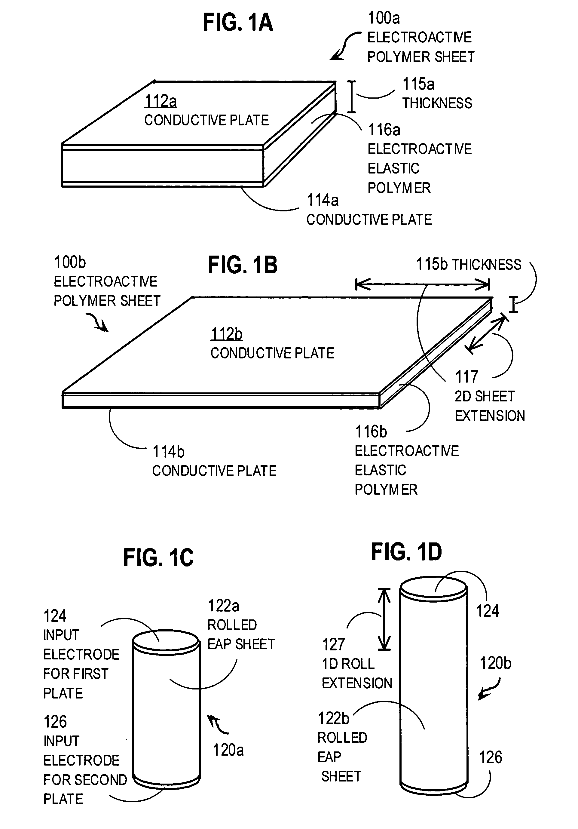
[0053] As described in Pelrine I and illustrated in FIG. 1A and FIG. 1B, an electr...


PUM


Abstract

A motor includes a support framework and a mechanical movement component moveably mounted to the support framework. An electroactive polymer device having a pair of input electrodes is configured to deform upon application of an electric potential difference across the pair of input electrodes. The electroactive polymer device is mechanically linked to the support framework and to the mechanical movement component so that deformation of the electroactive polymer device causes the movement component to move relative to the support framework. In some motors, the movement component and an electrode fixed in the support framework are driven at different electrical potentials to cause the electroactive polymer device to deform. In some motors a rolled electroactive polymer device is used with a rotating movement component. Such motors enable lightweight, powered vehicles with low radar reflectivity.

Description

CROSS-REFERENCE TO RELATED APPLICATIONS [0001] This application claims benefit of U.S. Provisional Application 60 / 539,680, filed Jan. 28, 2004, the entire contents of which are hereby incorporated by reference as if fully set forth herein, under 35 U.S.C. §119(e). [0002] This application is related to U.S. non-provisional application Ser. No. ______ (Attorney Docket No. 2118-SPL) filed on even date herewith by inventor Jerry A. Krill, entitled “Variable Ratio Transmission Elements for Motor Drive Shafts,” which is incorporated herein by reference in its entirety.BACKGROUND OF THE INVENTION [0003] 1. Field of the Invention [0004] The present invention relates to dielectric motors; and in particular to dielectric motors that use charged moving components, or a rolled electro-active polymer (EAP) to generate rotating mechanical motion, or both, and vehicles that employ such motors. [0005] 2. Description of the Related Art [0006] Conventional electric motors and combustion engines are w...

Claims


Application Information

Patent Timeline
Patent Type & Authority Applications(United States)
IPC IPC(8): H01L41/09H02N2/04H02N11/00
CPCH02N2/10Y10S310/80H02N11/006H02N2/101
Inventor KRILL, JERRY A.
Owner THE JOHN HOPKINS UNIV SCHOOL OF MEDICINE
Why Eureka
Try Eureka