Clad pipe

a technology of clad pipe and spherical pipe, which is applied in the direction of drilling pipes, packaging, and synthetic resin layered products, can solve the problems of forming the entire thickness of the pipe by high alloy, increasing cost, and bending of the pipe, and achieves excellent corrosion resistance against hydrogen sulfide, easy welding, and less cost.

Inactive Publication Date: 2005-08-04
DAI ICHI HIGH FREQUENCY
View PDF1 Cites 45 Cited by
  • Summary
  • Abstract
  • Description
  • Claims
  • Application Information

AI Technical Summary

Benefits of technology

[0018] One effects of the present invention is that the clad pipe is excellent in corrosion resistance against hydrogen sulfide. Another effect is that the clad pipe is less expensive than a pipe entirely made of high alloy. Another effect is that the clap pipes can be easily welded to obtain a long tube having a desired length (for example, screw joint can be performed.) Another effect is that the ware status of the inner coated layer of the clad pipe can be measured from the outside of the pipe in a nondestructive manner.

Problems solved by technology

However, forming the entire thickness of the pipe by high alloy causes significantly increased cost, and therefore a clad pipe (double pipe), or a carbon steel pipe with an inner layer made of high alloy, has been normally used.
One problem associated with this structure (i.e., build-up welding) is that since the build-up welding is performed on the inner surface of a long pipe, bending of the pipe occurs.
Another problem is that, in the case of build-up welding, a diluted layer of the base material components and the build-up welding components is formed at the boundary portion between the base material of the steel pipe and the build-up welded layer.
In order to form a build-up welding layer containing prescribed components with a predetermined thickness, it is necessary to further build-up a welding layer corresponding to the thickness of the diluted layer, which increases cost.
Still another problem is that, due to the existence of the diluted layer, there is no clear boundary between the base material and the build-up welded layer.
As a result, it is difficult to measure the wear status of the build-up welding layer from the outside of the pipe in a nondestructive manner.
Because of this, it is required to strictly control processing tolerance of the inner and outer diameters thereof, which in turn increases manufacturing costs.
Another problem with this structure is that it is difficult to manufacture a long article.

Method used


Image

  • Clad pipe
  • Clad pipe
  • Clad pipe

Examples


Embodiment Construction

[0030] Embodiments of the invention will be described hereinafter with reference to the accompanying figures. It should be understood based on this disclosure that various other modifications can be made by those in the art based on these illustrated embodiments.

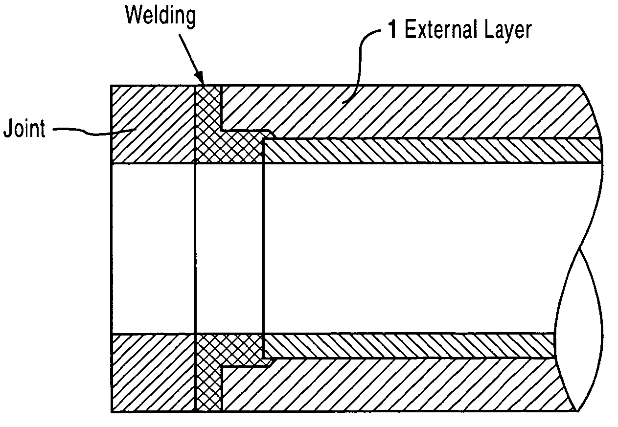
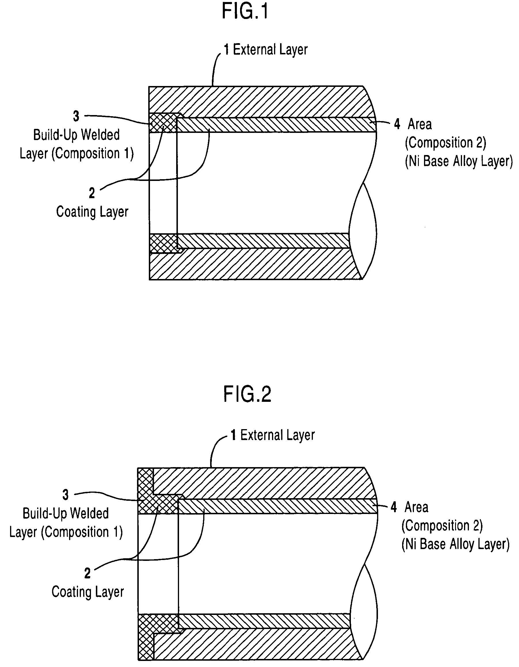
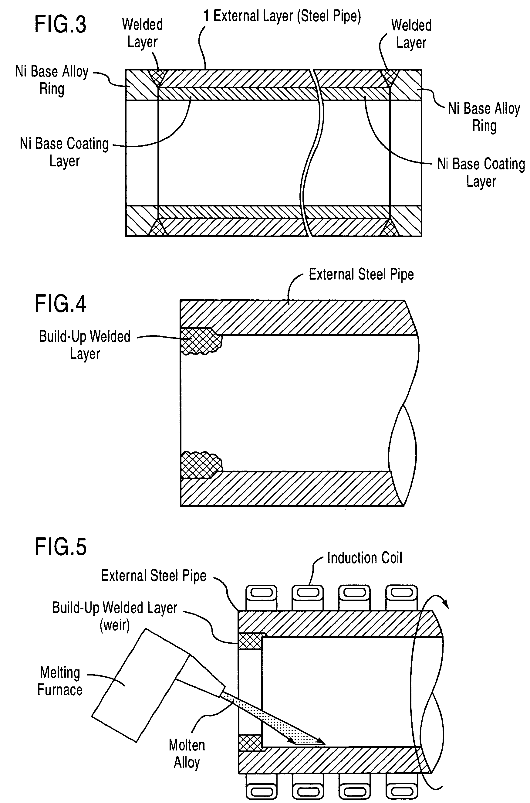
[0031] FIGS. 1 to 3 are explanatory views showing basic structures of clad pipes according to preferred embodiments of the present invention. In FIGS. 1 and 2, an external layer 1 is constituted by a carbon steel pipe or a low alloy steel pipe, and a clad layer 2 is made of Ni base anticorrosion alloy. The both end portions of the clad layer 2 are formed by build-up welding (Ni base alloy of composition 1).

[0032] The section (area 4) of the clad layer 2 located between the build-up welded layers 3 formed at both end portions of the tube is made of Ni base alloy (Ni base alloy of composition 2) having a composition in which solidus-curve temperature is 1300° C. or less and lower than the solidus-curve temperature of the Ni ...


PUM

PropertyMeasurementUnit
solidus-curve temperatureaaaaaaaaaa

Abstract

A clad pipe includes an external layer and a coating layer made of Ni base anticorrosion alloy. Both end portion areas of the coating layer are formed by a build-up welded layer (Ni base alloy of composition 1) on the inner surface of the external layer. Other areas are formed by a Ni base alloy layer (Ni base alloy of composition 2) fusion-bonded to the build-up welded layers and the inner surface of the pipe, a solidus-curve temperature of the Ni base alloy layer being 1300° C. or below and lower than a solidus-curve temperature of the Ni base alloy formed by build-up welding by 150° C. or more. Composition 1 and composition 2 are adjusted so that, in the same environment, corrosion resistance of the Ni base alloy of composition 1 is equivalent to or superior to that of the Ni base alloy of composition 2.

Description

[0001] This application claims priority under 35 U.S.C.§ 119 to Japanese Patent Application No. 2004-24951 filed on Feb. 2, 2004 and Japanese Patent Application No. 2004-348161 filed on Dec. 1, 2004, the entire disclosure of which are incorporated herein by reference in their entireties. FIELD OF THE INVENTION [0002] The present invention relates to a structure of a clad pipe excellent in corrosion resistance, and more specifically to a structure of a clad pipe with an inner surface covered by Ni-base alloy excellent in corrosion resistance against hydrogen sulfide, etc., which is preferably used as, for example, an oil pipe and an oil well tubular. In this disclosure, the wording of “%” used to define alloy composition denotes “mass %”. BACKGROUND OF THE INVENTION [0003] It is known that oil and gas fields, rich in corrosive components, such as hydrogen sulfide, lie under the ground. In an oil well pipe including an oil pipeline / oil well tubular used to mine or transport oil and / or...

Claims


Application Information

Patent Timeline
Patent Type & Authority Applications(United States)
IPC IPC(8): B21C37/15B22D13/02B22D19/16B23K9/04B23K9/00B23K35/30B23K101/06B23K103/18B32B1/08B32B15/18C22C19/05C22C38/00C22C38/44C22F1/00C22F1/10C23C4/08C23C4/12E21B17/00F16L58/08
CPCB21C37/154Y10T428/12854B23K2201/06B23K2201/34C23C4/08C23C4/121E21B17/00F16L58/08Y10T428/12493Y10T428/1352Y10T428/12944Y10T428/13Y10T428/12937Y10T428/12951B23K35/304C23C4/123B23K2101/06B23K2101/34
Inventor MATSUBARA, YOICHITAKEYA, AKIHIROMIYATA, SEIICHIRO
Owner DAI ICHI HIGH FREQUENCY
Why Eureka
Try Eureka