Plasma reactor with minimal D.C. coils for cusp, solenoid and mirror fields for plasma uniformity and device damage reduction

Active Publication Date: 2005-08-04
APPLIED MATERIALS INC
View PDF99 Cites 40 Cited by
  • Summary
  • Abstract
  • Description
  • Claims
  • Application Information

AI Technical Summary

Benefits of technology

[0012] The processor can be programmed to search for the best combination of D.C. currents for the three magnets to improve plasma ion density distribution

Problems solved by technology

In fact, a problem in fabricating high aspect ratio microelectronic integrated circuits is that non-uniformities in the plasma ion density across the workpiece surface can lead to process failure due to non-uniform etch rates or deposition rates.
Nevertheless, such reactors have non-uniform plasma density distributions.
Typically, the radial density distribution of plasma ions is high over the center of the wafer support and low near the periphery, a significant problem.
This approach has certain limitations.
In particular, the strength of the magnetic field may need to be limited in order to avoid device dama

Method used


Image

  • Plasma reactor with minimal D.C. coils for cusp, solenoid and mirror fields for plasma uniformity and device damage reduction
  • Plasma reactor with minimal D.C. coils for cusp, solenoid and mirror fields for plasma uniformity and device damage reduction
  • Plasma reactor with minimal D.C. coils for cusp, solenoid and mirror fields for plasma uniformity and device damage reduction

Examples


Embodiment Construction

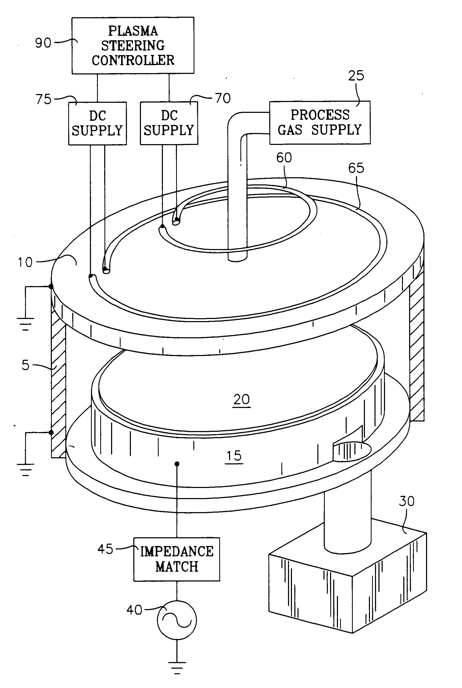
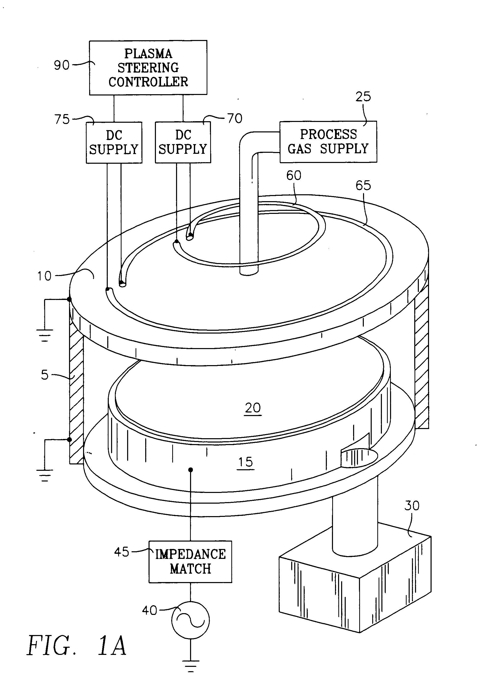
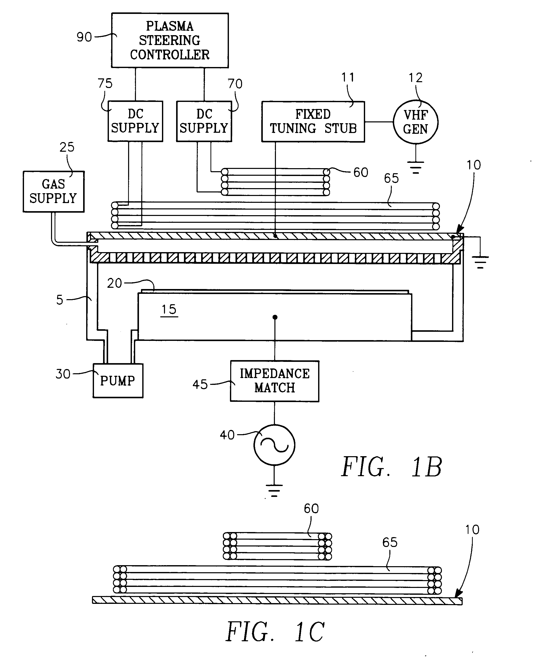
[0070] The plasma ion density distribution exhibited by a particular plasma reactor is a function of chamber pressure, gas mixture and diffusion, and source power radiation pattern. In the present reactor, this distribution is magnetically altered to approximate a selected or ideal distribution that has been predetermined to improve process uniformity. The magnetically altered or corrected plasma ion density distribution is such that process uniformity across the surface of the wafer or workpiece is improved. For this purpose, the magnetically corrected plasma distribution may be non-uniform or it may be uniform, depending upon the needs determined by the user. We have discovered that the efficiency with which an average magnetic field strength exerts pressure on a plasma to change its distribution to a desired one can be improved. This surprising result can be achieved in accordance with this discovery by increasing the radial component of the gradient of the magnetic field. The ra...


PUM

PropertyMeasurementUnit
Timeaaaaaaaaaa
Diameteraaaaaaaaaa
Magnetic fieldaaaaaaaaaa

Abstract

A plasma reactor for processing a workpiece, includes a vacuum chamber defined by a sidewall and ceiling, and a workpiece support pedestal having a workpiece support surface in the chamber and facing the ceiling and including a cathode electrode. An RF power generator is coupled to the cathode electrode. Plasma distribution is controlled by an external annular inner electromagnet in a first plane overlying the workpiece support surface, an external annular outer electromagnet in a second plane overlying the workpiece support surface and having a greater diameter than the inner electromagnet, and an external annular bottom electromagnet in a third plane underlying the workpiece support surface. D.C. current supplies are connected to respective ones of the inner, outer and bottom electromagnets.

Description

CROSS-REFERENCE TO RELATED APPLICATIONS [0001] This application is a continuation-in-part of U.S. application Ser. No. 10 / 841,116, filed May 7, 2004 entitled CAPACITIVELY COUPLED PLASMA REACTOR WITH MAGNETIC PLASMA CONTROL by Daniel Hoffman, et al., which is divisional of U.S. application Ser. No. 10 / 192,271, filed Jul. 9, 2002 entitled CAPACITIVELY COUPLED PLASMA REACTOR WITH MAGNETIC PLASMA CONTROL by Daniel Hoffman, et al., all of which are assigned to the present assignee.BACKGROUND [0002] Capacitively coupled plasma reactors are used in fabricating semiconductor microelectronic structures with high aspect ratios. Such structures typically have narrow, deep openings through one or more thin films formed on a semiconductor substrate. Capacitively coupled plasma reactors are used in various types of processes in fabricating such devices, including dielectric etch processes, metal etch processes, chemical vapor deposition and others. Such reactors are also employed in fabricating p...

Claims


Application Information

Patent Timeline
IPC IPC(8): H01J37/32
CPCH01J37/32091H01J37/3266H01J37/32623H01J37/3244E01C19/178E01C11/24
Inventor HOFFMAN, DANIEL J.LINDLEY, ROGER A.KUTNEY, MICHAEL C.SALINAS, MARTIN J.TAVASSOLI, HAMID F.HORIOKA, KEIJIBUCHBERGER, DOUGLAS A. JR.
Owner APPLIED MATERIALS INC
Why Eureka
Try Eureka