
Method for forming Re-Cr alloy film through electroplating process using bath containing Cr(VI)

a technology of re-cr alloy and electroplating process, which is applied in the field of forming a re-cr alloy, can solve the problems of large-scale apparatus and complicated operations, large number of defects or cracks in the obtained film, and many restrictions on the size and shape of the substrate, so as to improve the plating efficiency and reduce the occurrence of defects

Inactive Publication Date: 2005-08-04
JAPAN SCI & TECH CORP +2
View PDF5 Cites 0 Cited by
  • Summary
  • Abstract
  • Description
  • Claims
  • Application Information

AI Technical Summary

Benefits of technology

[0011] It is still another object of the present invention to provide a method capable of forming a Re—Cr alloy film through an electroplating process at a low cost in a simplified manner as compared to the physical deposition process and the thermal spraying process.
[0017] Further, in the method of the present invention, the plating bath may contain a chromium (III) ion in a concentration of 0.0001 to 0.03 mol / L and / or a sulfate ion in a concentration of 0.0001 to 0.03 mol / L. These substances act as a catalytic agent for electrolytic deposition of Cr to improve the plating efficiency and educe the occurrence of spots in a plated film. This effect cannot be obtained by a concentration of chromium (III) ion or sulfate ion less than 0.0001 mol / L, and the use of a concentration of chromium (III) ion or sulfate ion grater than 0.03 mol / L has the opposite effect or causes deterioration in current efficiency. Therefore, the concentration of the chromium (III) ion or sulfate ion is preferably set in the range of 0.0001 to 0.03 mol / L.

Problems solved by technology

On the other hand, it involves problems, such as, (i) many restrictions on the size and shape of a substrate, (ii) the need for a large-scaled apparatus and complicated operations and (iii) a relatively large number of defects or cracks in an obtained film.
A thermal spraying process involves problems, such as, (i) a relatively large number of defects in an obtained film, (ii) lack of compatibility to the formation of thin films (10 μm or less) and (iii) poor process yield and low economical efficiency.

Method used


Image

  • Method for forming Re-Cr alloy film through electroplating process using bath containing Cr(VI)
  • Method for forming Re-Cr alloy film through electroplating process using bath containing Cr(VI)

Examples


##ventive example 1

INVENTIVE EXAMPLE 1

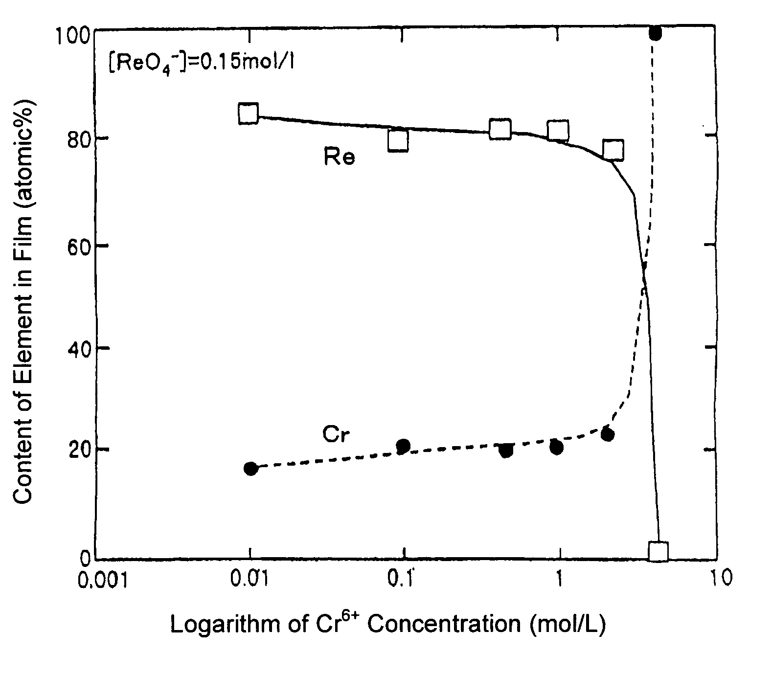
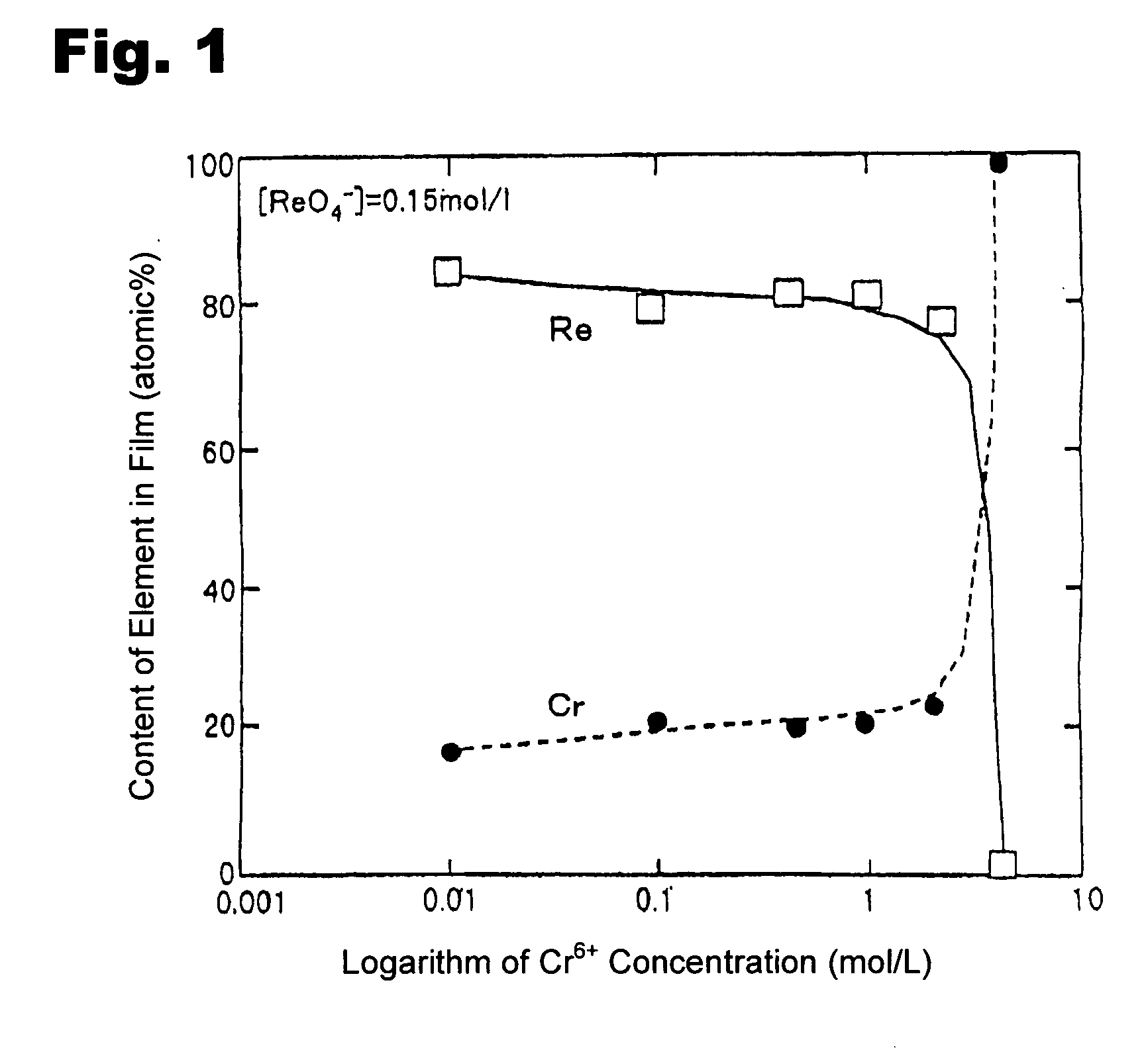
[0019] A copper plate was subjected to degreasing / cleaning, and used as a substrate. A solution was prepared using chromic anhydride to have a Cr6+ ion in a concentration of 0.01 mol / L In addition to the Cr6+ ion, 0.15 mol / L of ReO4−, 0.01 mol / L of chromium chloride, and 0.01 mol / L of sulfuric acid were added to the solution to prepare a plating bath. The pH of the plating bath was adjusted at 0 (zero). Then, an electroplating process was performed for 1 hour under a plating bath temperature of 50° C. and a current density of 100 mA / cm2.

##ventive example 2

INVENTIVE EXAMPLE 2

[0020] Except that the concentration of the Cr6+ was set at 0.1 mol / L, an electroplating process was performed under the same conditions as those in Inventive Example 1.

##ventive example 3

INVENTIVE EXAMPLE 3

[0021] Except that the concentration of the Cr6+ was set at 0.5 mol / L, an electroplating process was performed under the same conditions as those in Inventive Example 1.


PUM

PropertyMeasurementUnit
temperatureaaaaaaaaaa
pHaaaaaaaaaa
temperatureaaaaaaaaaa

Abstract

Disclosed is a method for forming a Re—Cr alloy film consisting of Re in the range of 60 to 90% by atomic composition. The method comprises performing an electroplating process using an electroplating bath containing an aqueous solution which includes a perrhenate ion and a chromium (IV) ion. The present invention allows a Re—Cr alloy film usable as a corrosion-resistant alloy coating for a high-temperature component or the like to be formed through an electroplating process using an aqueous solution, so as to provide heat / corrosion resistances to the component, even if it has a complicated shape, in a simplified manner at a low cost.

Description

TECHNICAL FIELD [0001] The present invention relates to a method for forming a Re—Cr alloy usable as a corrosion-resistant coating for high-temperature components or the like. BACKGROUND ART [0002] A Ni-based superalloy substrate for use in a blade for jet engines, gas turbines or the like is strictly required to have high oxidation resistance and corrosion resistance. Such required high-temperature oxidation resistance has been obtained through a surface diffusion treatment, for example, by coating a substrate surface with an Al2O3 film. For covering the insufficient performance of this treatment, there has also been developed a technique for forming a diffusion barrier layer of Pt or the like on a substrate. Rhenium (Re) can be used as the diffusion barrier layer to provide enhanced high-temperature corrosion resistance. Re excellent in thermal shock resistance is also used as high-temperature members or components of various combustors, such as a rocket-engine combustor, or high-...

Claims


Application Information

Patent Timeline
Patent Type & Authority Applications(United States)
IPC IPC(8): C25D3/56
CPCC25D3/56
Inventor NARITA, TOSHIOHAYASHI, SHIGENARIYOSHIOKA, TAKAYUKIYAKUWA, HIROSHISOUMA, MICHIAKI
Owner JAPAN SCI & TECH CORP
Learn More