Method and apparatus reducing electrical and thermal crosstalk of a laser array

a laser array and electrical and thermal crosstalk technology, applied in the field of lasers, can solve the problems of reducing the yield of manufacturers, affecting the operation performance of laser arrays, and limiting the capacity of optical communication systems, so as to achieve the effect of improving the yield of manufacturers and improving the operating performan

Inactive Publication Date: 2005-08-04
QUANTUM DEVICES
View PDF5 Cites 45 Cited by
  • Summary
  • Abstract
  • Description
  • Claims
  • Application Information

AI Technical Summary

Benefits of technology

[0008] The invention provides techniques for active compensation for a semiconductor laser array. Active compensation can be used for control of temperature, wavelength, and other characteristics of the lasers within the laser array. Through active compensation, operating performance and manufacturer yields can be improved.

Problems solved by technology

While demand for bandwidth soars, this one optical wavelength per optical fiber design has limited the capacity of optical communications systems.
Unfortunately, several problems can render the use of simultaneously driven WDM laser arrays impractical.
One problem with conventional WDM laser arrays is the shift in laser wavelengths caused by changes in temperature at the laser sites when one or more particular lasers are turned “on” (i.e., selected for use) or “off” (i.e., deselected).
Typically, the data bit rate is high and results in an average duty cycle of approximately fifty percent and a steady-state power dissipation of approximately one half peak power.
The problematic temperature change generally occurs when one or more lasers is “deselected” (i.e., the data stream input to the laser is removed).
Specifically, the problem arises because the operating wavelength of semiconductor lasers is dependent on temperature.
Unfortunately, because of the substantial power levels at which WDM lasers typically operate (e.g., PL=0.2 to 0.5 watts per laser), when one or more lasers in the array are deselected, the thermal crosstalk between these devices in practical array packaging configurations leads to temperature changes much greater than the allowable temperature range.
This problem makes it extremely difficult to use laser arrays in applications (e.g., WDM) involving simultaneous and selectable operation of lasers in the array.
In fact, for many applications, this problem can preclude the use of laser arrays altogether.
Another problem with conventional WDM laser arrays relates to manufacturing yields.
However, with an array of lasers sharing only one TE cooler / controller, the temperature of each of the lasers cannot be independently adjusted to obtain the specified operating wavelengths for all lasers.
This translates to poor manufacturing yields and increased costs for WDM laser arrays, as compared to individually packaged devices.
The poor manufacturing yields make the use of laser arrays prohibitively expensive.

Method used


Image

  • Method and apparatus reducing electrical and thermal crosstalk of a laser array
  • Method and apparatus reducing electrical and thermal crosstalk of a laser array
  • Method and apparatus reducing electrical and thermal crosstalk of a laser array

Examples


Embodiment Construction

Laser Array

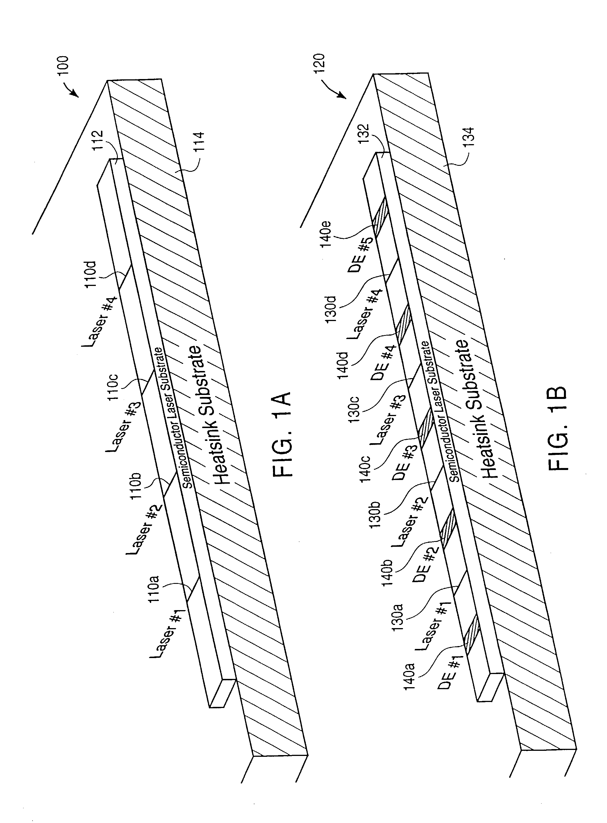
[0026]FIG. 1A is a diagram of a conventional laser array 100. As shown in FIG. 1A, laser array 100 includes four lasers 110a through 110d. The four-laser array (NL=4) is shown by way of example. Other laser arrays can include more or fewer lasers. Each laser 110 is a narrow multi-layer diode strip (e.g., typically a few microns in width) formed in the top few microns of a semiconductor laser substrate 112 that is, for example, approximately 100 microns in thickness. Laser substrate 112 sits on top of a heat sink substrate 114. Semiconductor laser substrate 112 is also referred to as a laser array bar. Lasers 110 are typically equally spaced apart (e.g., by approximately 0.25, 0.50, 0.75, or 1.0 mm).

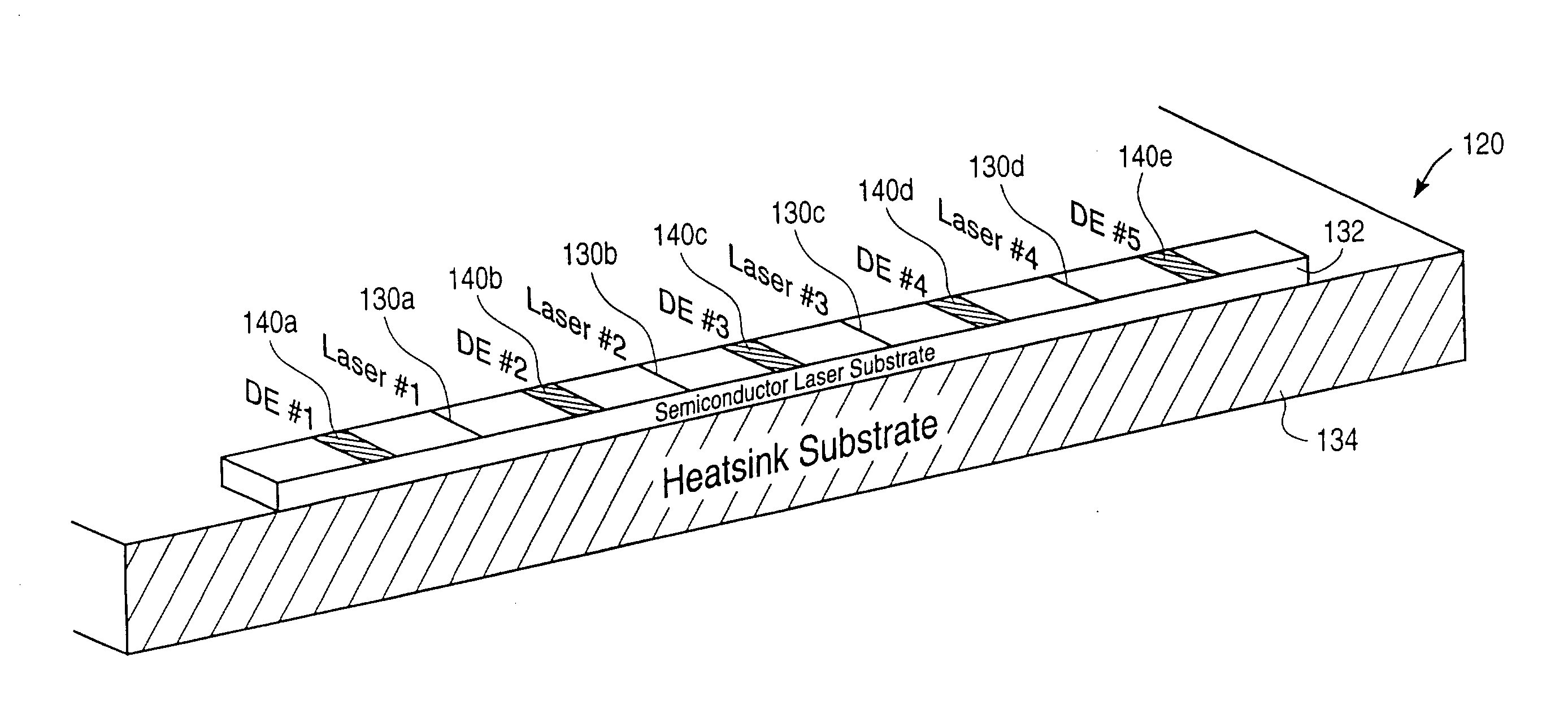
[0027]FIG. 1B is a diagram of a laser array 120 of the invention. As shown in FIG. 1B, laser array 120 also includes four lasers 130a through 130d that are dimensioned and evenly spaced similar to those in laser array 100. However, laser array 120 further includes five “dumm...


PUM


Abstract

Active compensation techniques are used for control of temperature, wavelength, and other characteristics of lasers within a laser array. The laser array includes a plurality of lasers and a plurality of dissipation elements. The dissipation elements can be interstitial to the lasers and can be implemented as non-lasing diodes. The dissipation elements are selectively activated (i.e., turned “on” to dissipate power) to adjust the temperature at the laser junctions. The change in junction temperature allows the lasers to operate at their specified wavelengths. The dissipation elements can be individually controlled and two or more bits of resolution can be provided. Active compensation can be used to adjust (i.e., to compensate) the temperature of selected lasers when one or more lasers are deselected. Active compensation can also be used to adjust (i.e., “tweak”) the wavelengths of the lasers within the laser array to be within their specified wavelengths.

Description

BACKGROUND OF THE INVENTION [0001] This invention relates to lasers, and in particular to a method and apparatus for providing active compensation for a semiconductor laser array. Active compensation can be used for control of temperature, wavelength, and other characteristics of each individual laser within the laser array. [0002] Optical communications systems are used to provide high-speed communication, including voice and data services. Conventionally, only one optical signal at one wavelength (or one channel) is transmitted per optical fiber. While demand for bandwidth soars, this one optical wavelength per optical fiber design has limited the capacity of optical communications systems. [0003] Wavelength division multiplexing (WDM) is a technology that greatly increases the information transmission capacity of optical fibers in communications systems. In a WDM system, a multiplicity of independently modulated lasers, each with a unique but precisely controlled wavelength, gene...

Claims


Application Information

Patent Timeline
Patent Type & Authority Applications(United States)
IPC IPC(8): H01S5/40
CPCH01S5/4025H01S5/4031H01S5/02216H01S5/0224H01S5/4087H01S5/02284H01S5/0427H01S5/06226H01S5/06804H01S5/02276H01L2224/48091H01L2224/48472H01S5/02251H01S5/0234H01S5/02345H01L2924/00014
Inventor EDEN, RICHARD C.MAZED, MOHAMMAD A.
Owner QUANTUM DEVICES
Why Eureka
Try Eureka