Transmission type photoelectric cathode and electron tube

a photoelectric cathode and electron tube technology, applied in the field of transmission-type photoelectric cathodes and electron tubes, can solve the problems of deterioration of the p/n junction or schottky junction thereof, difficulty in realizing a transmission-type photocathode formed of diamonds, and inability to operate stably, so as to achieve a higher brightness and low power consumption

Inactive Publication Date: 2005-08-11
HAMAMATSU PHOTONICS KK
View PDF13 Cites 15 Cited by
  • Summary
  • Abstract
  • Description
  • Claims
  • Application Information

AI Technical Summary

Benefits of technology

[0019] Still furthermore, the electron tube may be provided with a fluorescent material for emitting light upon incidence of electrons thereto, and the fluorescent material located at the position corresponding to an incident position of light to be detected to the transmission type photocathode is made to emit ligh

Problems solved by technology

Internal photoelectric effect elements such as an Si photodiode, etc., which have been hitherto used as photodetectors for ultraviolet light, etc., have a problem that p/n junction or Schottky junction thereof is deteriorated by incidence of strong ultraviolet light and they do not operate stably.
However, in actuality, it is difficult to form diamond film having such a s

Method used


Image

  • Transmission type photoelectric cathode and electron tube
  • Transmission type photoelectric cathode and electron tube
  • Transmission type photoelectric cathode and electron tube

Examples


first embodiment

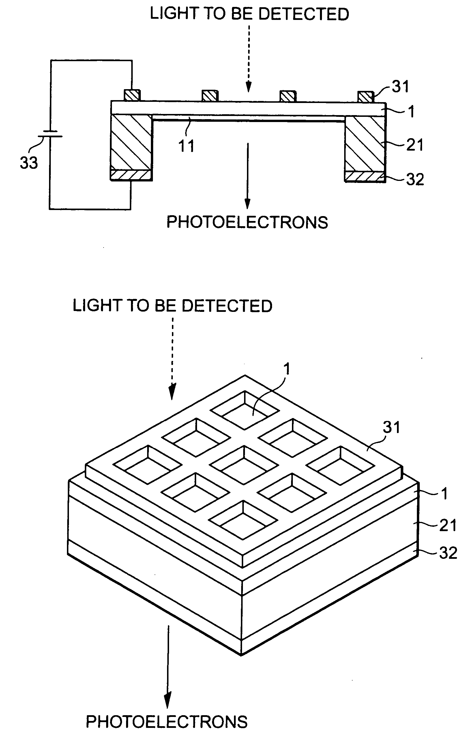
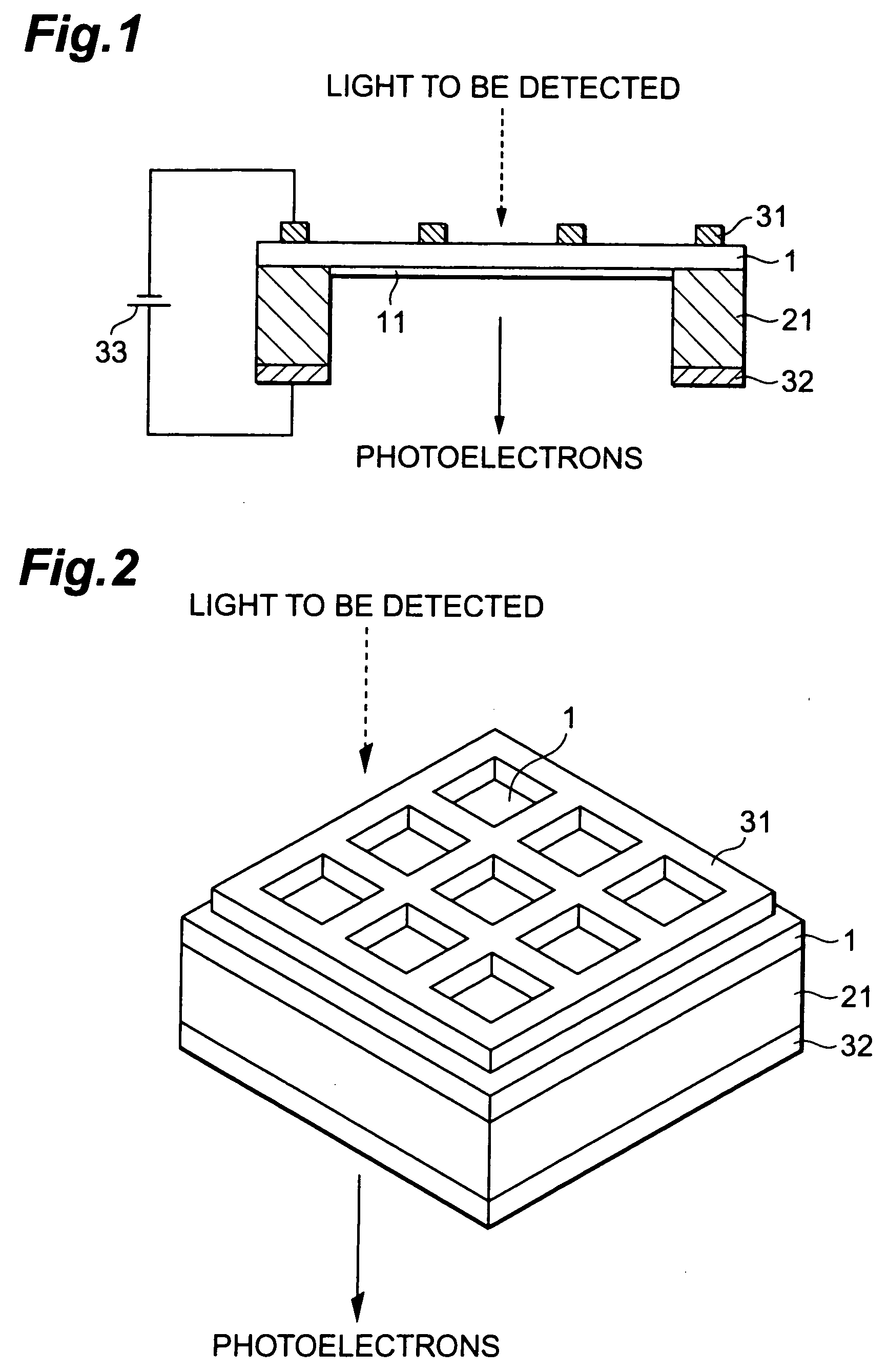
[0032]FIG. 1 is a side and cross-sectional view showing the construction of a transmission type photocathode of the present invention. FIG. 2 is a perspective view showing the transmission type photocathode shown in FIG. 1.

[0033] The transmission type photocathode shown in FIG. 1 comprises a light absorption layer 1, a supporting frame 21, a first electrode 31 and a second electrode 32. In the transmission type photocathode, photoelectrons are excited in the light absorption layer 1 upon incidence of light to be detected such as ultraviolet light or the like, and the photoelectrons thus excited are emitted to the outside. The transmission type photocathode has a transmission type structure that one surface of the light absorption layer 1 (the upper surface of FIG. 1) serves as a plane of incidence to which the light to be detected is made incident and the other surface at the opposite side of the light absorption layer 1 (the lower surface of FIG. 1) serves as a plane of emission fr...

second embodiment

[0056]FIG. 5 is a side and cross-sectional view showing the construction of the transmission type photocathode.

[0057] The transmission type photocathode shown in FIG. 5 comprises a light absorption layer 1, an active layer 11, a supporting frame 21, first electrode film 31a, an auxiliary electrode 34 and a second electrode 32. The constructions of the light absorption layer 1, the active layer 11, the supporting frame 21 and the second electrode 32 are the same as the transmission type photocathode shown in FIG. 1.

[0058] The first electrode film 31a is formed in a thin film form on the plane of incidence of the light absorption layer 1. The first electrode film 31a is formed to be extremely thin (about 30 to 150▭ in thickness). The auxiliary electrode 34 is formed on the first electrode film 31a for electrical connection to the first electrode film 31a formed in a thin film form.

[0059] The transmission type photocathode of this embodiment has the transmission type structure that o...

third embodiment

[0062]FIG. 6 is a side cross-sectional view showing the construction of the transmission type photocathode.

[0063] The transmission type photocathode shown in FIG. 6 comprises a light absorption layer 1, an active layer 11, a supporting frame 22, a first electrode 35 and a second electrode 36. The constructions of the light absorption layer 1 and the active layer 11 out of these elements are the same as the transmission type photocathode shown in FIG. 1.

[0064] The supporting frame 22 serves as supporting means for reinforcing the mechanical strength of the light absorption layer 1 which is formed to be thin. The supporting frame 22 is provided at the outer edge part on the plane of incidence of the light absorption layer 1.

[0065] The first electrode 35 is an incident plane side electrode provided at the plane of incidence of the light absorption layer 1. In this embodiment, the first electrode 35 is formed on the overall surface of the supporting frame 22 at the opposite side to th...


PUM


Abstract

A transmission type photocathode of the present invention comprises a light absorption layer 1 formed of diamond or a material containing diamond as a main component, a supporting frame 21 for reinforcing the mechanical strength of the light absorption layer 1, a first electrode 31 provided at the plane of incidence of the light absorption layer 1, and a second electrode 32 provided at the plane of emission of the light absorption layer 1. A voltage is applied between the plane of incidence and plane of emission of the light absorption layer 1 to form an electric field in the light absorption layer 1. When light to be detected is made incident and photoelectrons occur in the light absorption layer 1, the photoelectrons are accelerated to the plane of emission by the electric field formed in the light absorption layer 1, and emitted to the outside of the transmission type photocathode.

Description

FIELD OF THE ART [0001] The present invention relates to a photocathode for absorbing light to be detected to excite photoelectrons and emitting the photoelectrons thus excited to the outside, and an electron tube having the photocathode. BACKGROUND ART [0002] There have been hitherto known a photocathode used to detect light to be detected having a prescribed wavelength, and an electron tube having the photocathode. The photocathode has a light absorption layer for absorbing light having a prescribed wavelength and emitting photoelectrons. Light to be detected is made incident to the light absorption layer, and the incident light to be detected is converted to photoelectrons, whereby the light to be detected can be detected. Various kinds of semiconductor materials are used for the light absorption layer, and polycrystalline diamond has been disclosed as a material having a high quantum efficiency for photoelectrical conversion of ultraviolet light in Japanese Unexamined Patent App...

Claims


Application Information

Patent Timeline
IPC IPC(8): H01J1/34H01J31/50H01J40/06H01J43/08
CPCH01J1/34H01J2201/3421H01J31/506H01J31/50
Inventor NIIGAKI, MINORUUCHIYAMA, SHOICHIKAN, HIROFUMI
Owner HAMAMATSU PHOTONICS KK
Why Eureka
Try Eureka