Cathodoluminescent light source

a technology of cathodoluminescent light source and cathodoluminescent light source, which is applied in the direction of discharge tube luminescnet screen, electric discharge lamp, electrical apparatus, etc., can solve the problems of low efficiency of electric energy conversion into visible light in such devices, poor application restrictions of such devices, and use of mercury therein. , to achieve the effect of high electric energy conversion into ligh

Inactive Publication Date: 2005-08-11
OBRAZTSOV ALEXANDR NIKOLAEVICH
View PDF2 Cites 13 Cited by
  • Summary
  • Abstract
  • Description
  • Claims
  • Application Information

AI Technical Summary

Benefits of technology

[0008] It is a principal object of the present invention to provide a cathodoluminescent light source capable of ensuring as high electric energy conversion into light as possible.

Problems solved by technology

One of the most substantial disadvantages is use of mercury therein.
Efficiency of electric energy conversion into visible light in such devices is but too low on account of the fact that a considerable proportion of the energy must be spent for heating the cathode.
Furthermore, the fields of application of such devices are badly restricted by complicated production process thereof, as well as overall dimensions and requirements imposed upon operating conditions of said devices.
On the other hand use of other kinds of stimulated emission of electrons as a source thereof (such as photo-emission, secondary electron emission, and the like likewise fails to provide high-efficiency electric energy conversion into light.
Accordingly, voltage values accessible from practical standpoint involve provision of spires and blades of micron and sub-micron range which adds substantially to the cost of their production.
Moreover, electron emission occurs to be extremely unstable due to high sensitivity of such micron-size spire structures to environmental conditions.
Said circumstances impede substantially use of spire- and blade-type field-emission cathodes in broad-purpose apparatus and devices.
However, one of the disadvantages inherent in such a construction resides in that in order to provide an adequately high electric field intensity required for electron emission and the values of a voltage between the anode and cathode acceptable for practical use, one is forced to utilize threads having extremely small diameter (from 1μ to 15μ).
Too a low mechanical strength of such fine threads presents considerable problems in making cathodes for the light sources under consideration.
One more disadvantage of said construction of cathodoluminescent lamps lies with the fact that an electron beam performs a most efficient excitation on that side of the electron-excited phosphor layer which faces the cathode, that is, inwards the glass bulb.
Light absorption results in a loss of a part of energy and an affected general efficiency of lamps of a given type.
However, one of the disadvantages the lamps of said type suffer from is the use of carbon nanotubes whose production process involves utilization of a metallic catalyst.
Another disadvantage inherent in said lamps is the fact that subjected to electron excitation is also an electron-excited phosphor disposed on an inside surface of the cylinder-shaped glass bulb.
Part of the light emitted by said layer is absorbed when the light passes towards the transparent lamp surface, thereby affecting adversely a total efficiency of electric energy conversion into light.

Method used


Image

  • Cathodoluminescent light source
  • Cathodoluminescent light source
  • Cathodoluminescent light source

Examples


Embodiment Construction

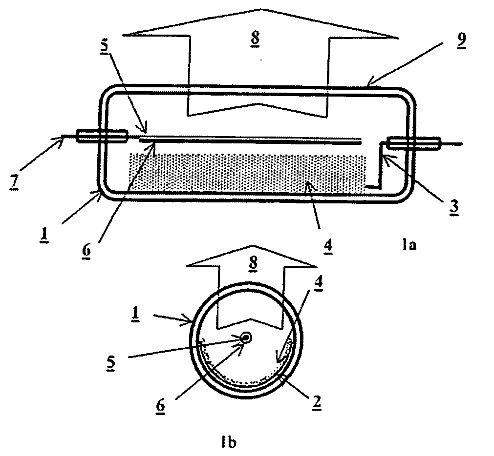
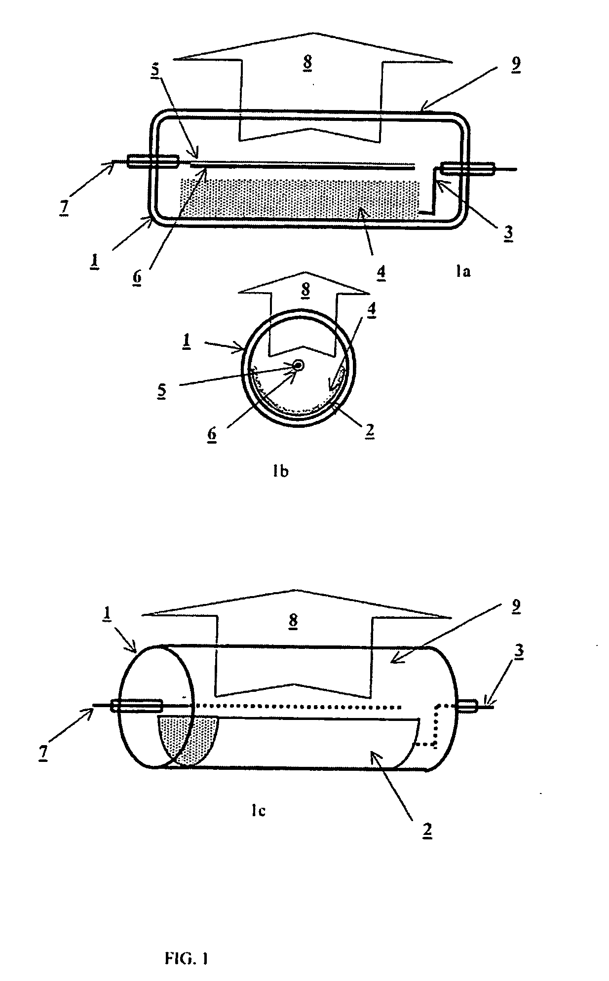
[0021] A cathodoluminescent lamp according to the invention may be shaped as a cylinder-shaped thermionic diode schematically shown in FIG. 1. To this end, first a cylinder-shaped glass bulb 1 is prepared, whereupon a layer 2 of aluminum or some other metal featuring good light-reflecting properties is applied to a portion of the inside cylinder-shaped bulb surface. Said reflecting metal layer is electrically connected to an electrode brought to the outside surface of a bulb 3. A layer 4 of an electron-excited phosphor is applied to said reflecting metal layer 2. The bulb 3 accommodates a field-emission cathode appearing as a cylinder-shaped metal wire 5 coated with a layer of a carbon material 6 featuring high-efficiency field electron emission. It is expedient to use as said carbon material a film consisting of a nanometric-size graphite crystallites and carbon nanotubes as taught in WO00 / 40508 A1. The cathode is reasonable to be arranged lengthwise the bulb longitudinal axis and ...


PUM


Abstract

A cathodoluminescent light source comprising a field-emission cathode serving as a source of electrons, an anode having a specular light-reflecting surface, and an electron-excited phosphor applied to the specular light-reflecting anode surface. The cathode and anode are enclosed in an evacuated housing having a transparent surface, so as to let the electron-excited phosphor on the anode surface, be irradiated with an electron beam, and let the luminous flux resulting from the process of cathodoluminescence, to emerge.

Description

TECHNICAL FIELD [0001] The present invention relates of sources of optical radiation used for lighting and / or forming images using displays of diverse constructions and purposes. BACKGROUND ART [0002] A variety of light sources are made use of virtually in every field of human activities. In an overwhelming majority of instances the operating principle of light sources implies electric current conversion into light. Depending on their specific use light sources should meet definite requirements as to radiation intensity and directivity, its spectral distribution, overall dimensions, and other characteristics. The most important parameter of any light source is the efficiency of electric energy conversion into light. Hence the parameters of the various light sources may vary within broad ranges depending on physical fundamentals used for light emission. In particular, said efficiency of electric energy conversion into visible light in incandescent lamps is as low as 15%. The efficien...

Claims


Application Information

Patent Timeline
Patent Type & Authority Applications(United States)
IPC IPC(8): H01J63/04H01J63/06
CPCH01J63/06
Inventor OBRATZSOV, ALEXANDER NIKOLAEVICH
Owner OBRAZTSOV ALEXANDR NIKOLAEVICH
Why Eureka
Try Eureka