
Phase-change recording material and information recording medium

a recording material and phase change technology, applied in the field of phase change recording materials and information recording media, can solve the problems of difficult to satisfy, significant noise of optical information recording medium, and significant noise of optical information recording medium, and achieve the effect of excellent recording signal characteristics and high storage stability of recording signals

Active Publication Date: 2005-08-11
CMC MAGNETICS CORPORATION
View PDF41 Cites 14 Cited by
  • Summary
  • Abstract
  • Description
  • Claims
  • Application Information

AI Technical Summary

Benefits of technology

[0009] For example, when the above composition which comprises a Sb70Te30 eutectic composition containing Sb in large excess and contains Ge is represented by (SbcTe1-c)1-dGed, it is possible to increase the crystallization speed by decreasing the ratio of the Te content relative to Sb by increasing the value c and bringing it to be close to 0.9. However, the noises of the optical information recording medium tend to be significant, and no favorable jitter characteristics will be obtained. Further, when the Ge content is reduced, although the noise increase tends to be suppressed the storage stability of the amorphous marks will decrease.
[0011] Under the above circumstances, the present inventors have conducted extensive studies and as a result, have found that when the Sb, In, Sn, Te and Ge compositions satisfy predetermined relational formulae, both recording signal quality such as the jitter characteristics and the stability of amorphous marks can be satisfied even if recording / erasing is carried out at a high velocity, and excellent recording signal characteristics can be maintained even when overwriting is carried out again after long term storage, and they have achieved the present invention.
[0019] The phase-change recording material of the present invention, by containing the composition represented by the formula (1) as the main component, is excellent in the recording signal characteristics even when recording / erasing is carried out at a high velocity, provides a high storage stability of the recording signals, provides a small decrease in the reflectivity of the recorded signals even after long term storage, and provides excellent recording signal characteristics even when overwriting is carried out again.
[0045] According to the present invention, a phase-change recording material on which high velocity recording / erasing is possible, which has excellent recording signal characteristics and which provides a high storage stability of the recording signals, and an information recording medium employing the above material can be provided.

Problems solved by technology

However, if the above phase-change recording material has a composition with which an adequately high crystallization speed is obtained, it tends to be difficult to satisfy both characteristics of excellent jitter characteristics (recording signal quality) and the storage stability of amorphous marks, from such a reason that noises of the signal of the optical information recording medium become significant.
This problem is particularly remarkable with an optical information recording medium on which high velocity recording / erasing of information signals is carried out at a reference clock period of at most 15 ns.
However, the noises of the optical information recording medium tend to be significant, and no favorable jitter characteristics will be obtained.

Method used


Image

  • Phase-change recording material and information recording medium
  • Phase-change recording material and information recording medium
  • Phase-change recording material and information recording medium

Examples


examples

[0328] Now, the present invention will be explained with reference to Examples wherein the phase-change recording material to be used in the present invention is applied to an optical information recording medium. However, the present invention is by no means restricted to the application to an optical information recording medium within a range not to exceed the gist of the present invention.

[0329] In the following Examples, an optical information recording medium may be referred to simply as “a disk”, “an optical disk”, “a phase-change type optical disk” etc. in some cases.

reference example 1

[0371] A disk of Reference Example 1 was prepared as follows.

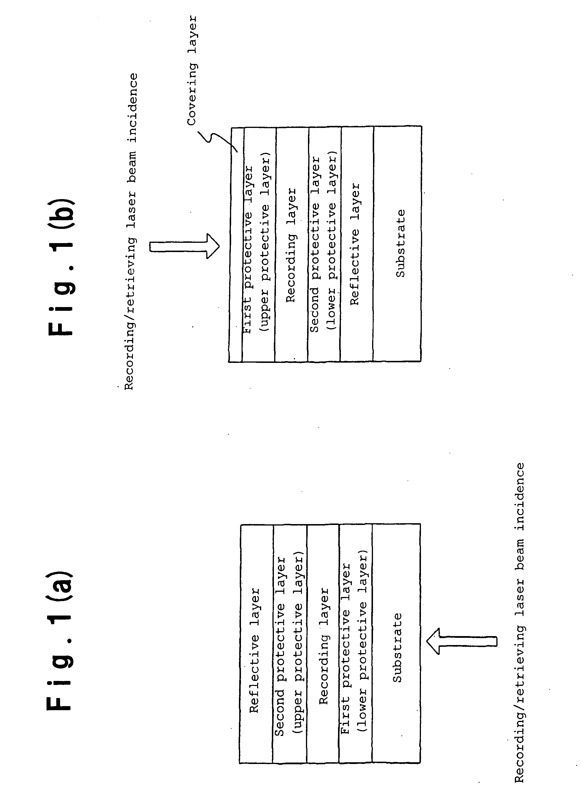
[0372] On a disk-shape polycarbonate substrate having a diameter of 120 mm and a thickness of 1.2 mm and having guide grooves with a groove width of 0.5 μm, a groove depth of 40 nm and a groove pitch of 1.6 μm, first to fifth layers were formed in order by a sputtering method as follows. The first layer is a (ZnS)80(SiO2)20 protective layer, the second layer is a recording layer, the third layer is a (ZnS)80(SiO2)20 protective layer, the fourth layer is a Ta interfacial layer, and the fifth layer is a Ag reflective layer. A protective layer comprising an ultraviolet-curing resin was further formed on these layers to prepare a phase-change type optical disk. The film thicknesses of the respective layers and the values x, y, z and w when the recording layer composition is represented by Gex(InwSn1-w)yTezSb1-x-y-z are shown in Table 2. Then, initial crystallization was carried out under the same conditions as in Example 1.

[...

examples 13 and 14

[0400] A polycarbonate resin substrate having a thickness of 0.6 mm and a track pitch of 0.74 μm was formed by injection molding and employed for the following experimental examples. Of the groove formed on the substrate, the groove width was about 0.31 μm, and the groove depth was about 28 nm. The groove shape was obtained by an optical diffraction method by U-groove approximation by means of a He—Cd laser beam having a wavelength of 441.6 nm.

[0401] Then, on the substrate, a (ZnS)80 (SiO2)20 protective layer of 40 nm, a (Y2O2S)90(ZnO)10 layer of 2 nm, a Ge7In6Sbs6Sn24Te7 recording layer of 10 nm, a (Y2O2S)90(ZnO)10 layer of 14 nm, a Ta interfacial layer of 2 nm, a Ag reflective layer of 200 nm and an ultraviolet-curing resin layer of about 4 μm were formed in this order. The Ta layer is an interfacial layer to prevent diffusion of S into the Ag reflective layer.

[0402] Formation of the respective layers was carried out by sequential deposition by a sputtering method on the substra...


PUM

PropertyMeasurementUnit
Timeaaaaaaaaaa
Thicknessaaaaaaaaaa
Thicknessaaaaaaaaaa

Abstract

A phase-change recording material on which high velocity recording / erasing is possible, which provides excellent recording signal characteristics, which provides a high storage stability of the recording signals, with which the change in the reflectivity of the recorded signals is small even after a long term storage, and which provides excellent recording signal characteristics even if overwriting is carried out again, and an information recording medium employing the above material, are provided. It is characterized by containing as the main component a composition represented by Gex(InwSn1-w)yTezSb1-x-y-z (wherein the Sb content is higher than any one of the Ge content, the In content, the Sn content and the Te content, and x, y, z and w representing atomicity ratios satisfy (i) 0≦x≦0.3, (ii) 0.07≦y-z, (iii) wxy-z≦0.1, (iv) 0<z, (v) (1−w)xy≦0.35 and (vi) 0.35≦1-x-y-z).

Description

TECHNICAL FIELD [0001] The present invention relates to a phase-change recording material and an information recording medium employing it. BACKGROUND ART [0002] As a recording method utilizing the phase change, a method has been known wherein the crystal structure of a metal or a semiconductor is reversibly changed by affecting energy beams or an energy flow such as light or electric current (Joule heat) (Appl. Phys. Lett., Vol. 18 (1971), pp. 254-257, U.S. Pat. No. 3,530,441). [0003] Used practically at present as a means for recording on an information recording medium employing a phase-change recording material, is a means to utilize a reversible change between the crystalline phase and the amorphous phase. Specifically, it is a means to let the crystalline state in a non-recorded / erased state and to form amorphous marks at the time of recording. Usually, a recording layer is locally heated to a temperature higher than the melting point and then rapidly cooled to form amorphous ...

Claims


Application Information

Patent Timeline
IPC IPC(8): B32B3/02G11B7/243G11B7/2433G11B7/257G11B7/258G11B7/259H01L45/00
CPCG11B7/00454Y10T428/21G11B7/2433G11B7/259G11B2007/2431G11B2007/24312G11B2007/24314G11B2007/24316G11B2007/25706G11B2007/2571G11B2007/25713G11B2007/25715G11B2007/25716H01L45/06H01L45/1233H01L45/126H01L45/148H01L45/1625Y10T428/24802G11B7/243H10N70/8413H10N70/231H10N70/884H10N70/026H10N70/826
Inventor OHNO, TAKASHIHORIE, MICHIKAZU
Owner CMC MAGNETICS CORPORATION
Learn More