Steam reforming system

a technology of steam reformer and steam pump, which is applied in the direction of mechanical equipment, machines/engines, energy input, etc., can solve the problems of reducing the radiant heat absorption efficiency of the reformer, increasing the size of the reformer, and reducing the average temperature of the combustion flue gas, so as to reduce the cost of the facility, increase the reformer size, and reduce the effect of radiant heat absorption efficiency

Inactive Publication Date: 2005-08-11
MITSUBISHI POWER LTD
View PDF7 Cites 15 Cited by
  • Summary
  • Abstract
  • Description
  • Claims
  • Application Information

AI Technical Summary

Benefits of technology

[0008] With the technique disclosed in JP,A 06-207531, the effect of cutting the fuel consumption in the reformer is expected, but a problem of increasing the reformer size arises because the increased amount of the combustion flue gases of the reformer leads to a reduction in the average temperature of the combustion flue gases, thereby reducing the radiant heat absorption efficiency of the reformer. Further, since the flue gases of the gas turbine have high temperatures in the range of 500-600° C., a flue gas duct endurable against such a high temperatures level is required to introduce the high-temperature flue gases to the reformer. When trying to minimize the facility cost, therefore, the reformer and the gas turbine must be installed close to each other. In such a case, the degree of freedom in plant layout is limited.
[0009] In the pre-reforming system, a part of the waste heat of the reformer, which has been used to generate steam in the past, is recovered as heat for heating the feedstocks up to the temperature suitable for the pre-reforming stage, and the effect of saving the fuel consumption in the reformer, which is obtained with the use of the pre-reformer, leads to a reduction in thermal value of the flue gases of the reformer. Accordingly, there arises a problem that the amount of steam generated from the reformer is reduced.
[0010] It is an object of the present invention to provide a steam reforming system with high thermal efficiency, which can compensate for a reduction in the amount of steam generated in a reformer without increasing the reformer size and without limiting the degree of freedom in layout of the reformer and a gas turbine.
[0011] To achieve the above object, according to the present invention, a gas turbine and a heat recovery exchanger are additionally

Problems solved by technology

With the technique disclosed in JP,A 06-207531, the effect of cutting the fuel consumption in the reformer is expected, but a problem of increasing the reformer size arises because the increased amount of the combustion flue gases of the reformer leads to a reduction in the averag

Method used


Image

  • Steam reforming system
  • Steam reforming system
  • Steam reforming system

Examples


first embodiment

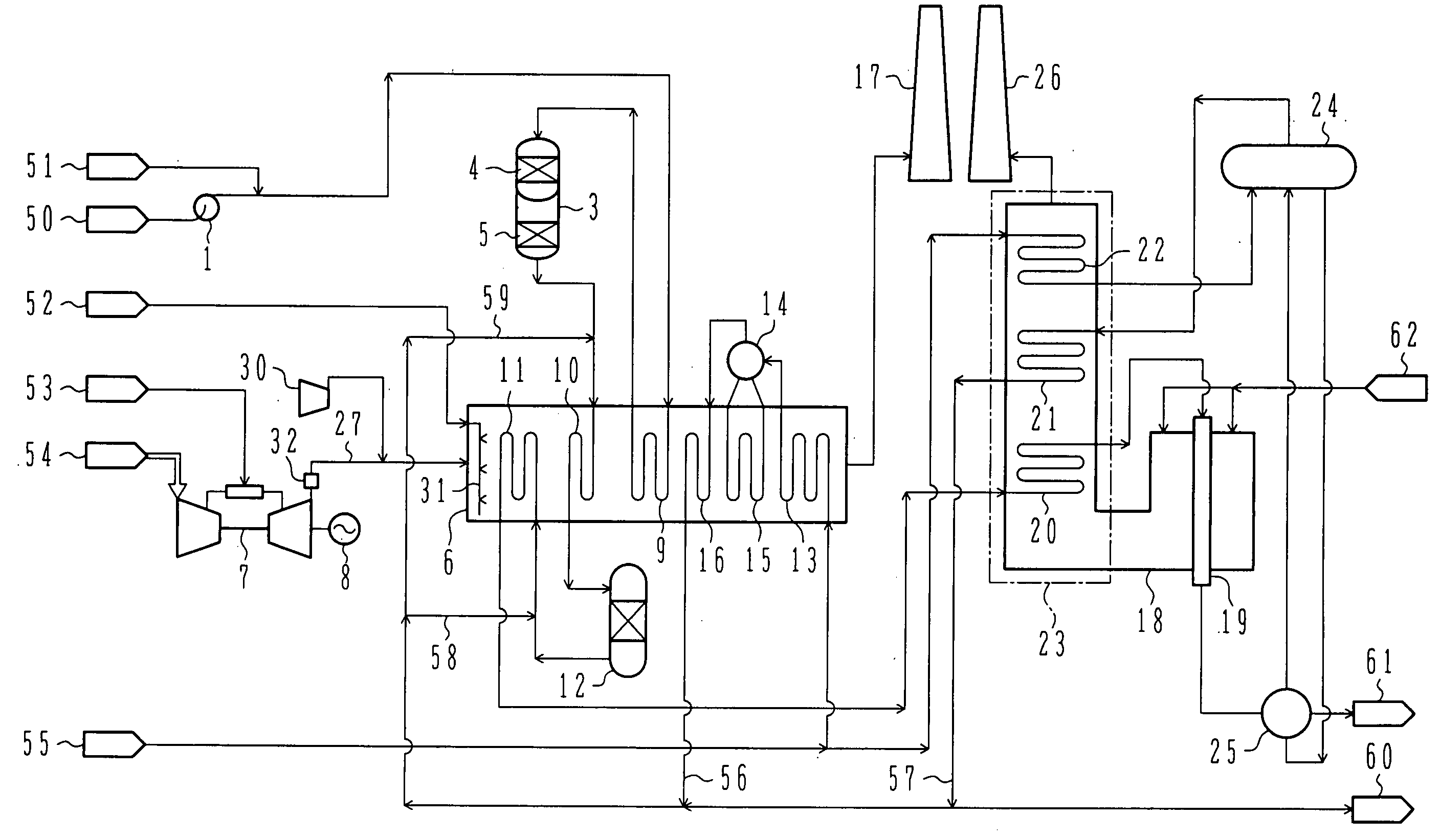
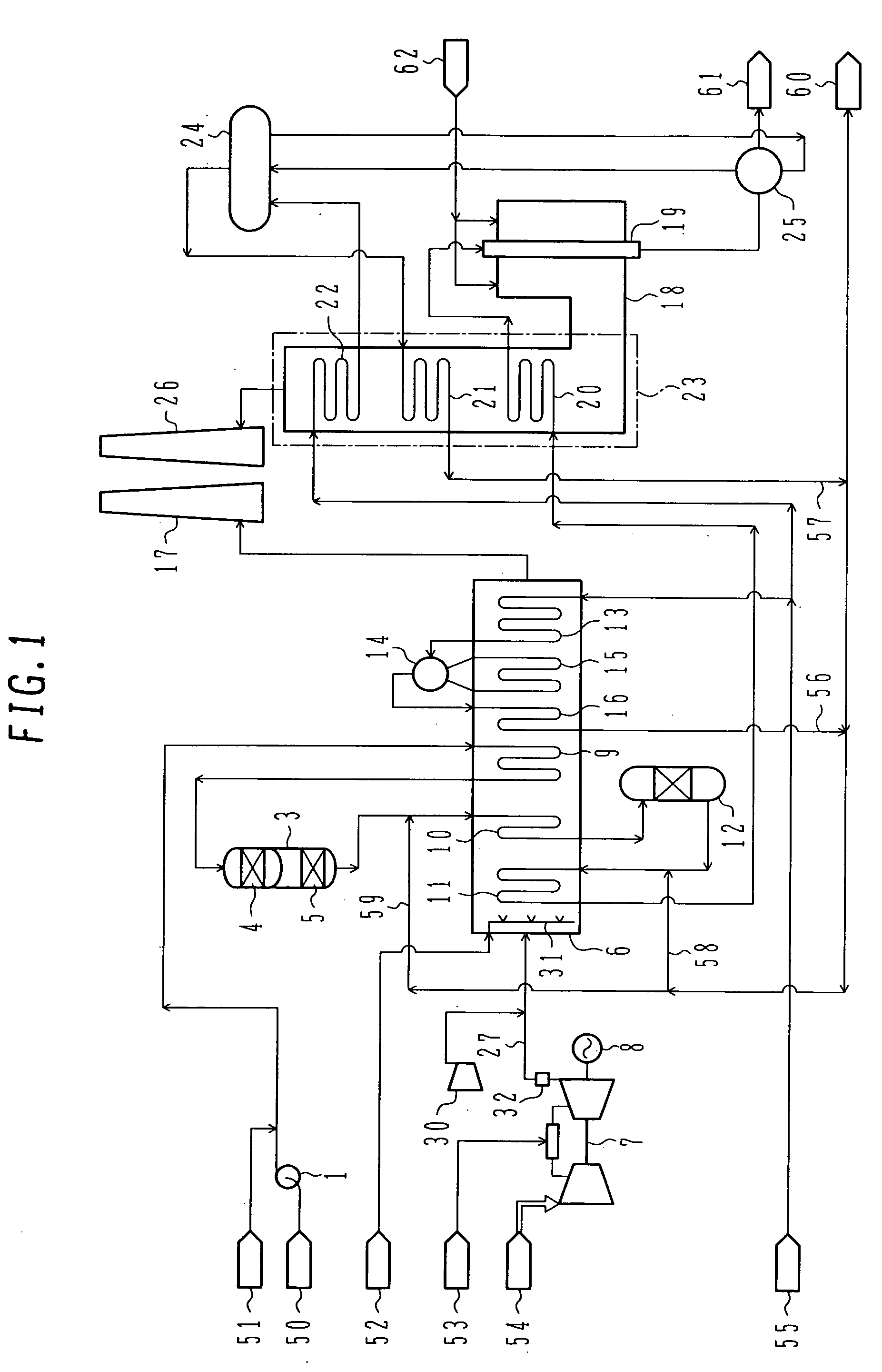
[0019]FIG. 1 shows a first embodiment of the present invention in which a pre-reformer and a gas turbine are additionally installed in combination with a conventional hydrogen production plant using naphtha as feedstocks.

[0020] Referring to FIG. 1, fuel 53 is supplied to a gas turbine 7 additionally installed in combination with a reformer 18, and a power generator 8 coupled to the gas turbine 7 generates electric power. Gas turbine (GT) flue gases are discharged from a chimney 17 through a GT flue gas duct 27 and a heat recovery exchanger 6. The GT flue gas duct 27 includes a damper 32 and a blower 30.

[0021] The heat recovery exchanger 6 comprises heat exchangers, such as an economizer 13, an evaporator 15, a superheater 16, a feed preheater 9 and feed heaters 10, 11, along with a steam drum 14 and an auxiliary burner 31.

[0022] In the heat recovery exchanger 6, the feed preheater 9 and the feed heaters 10, 11 perform heat exchange between the GT flue gases and feedstocks supplie...

second embodiment

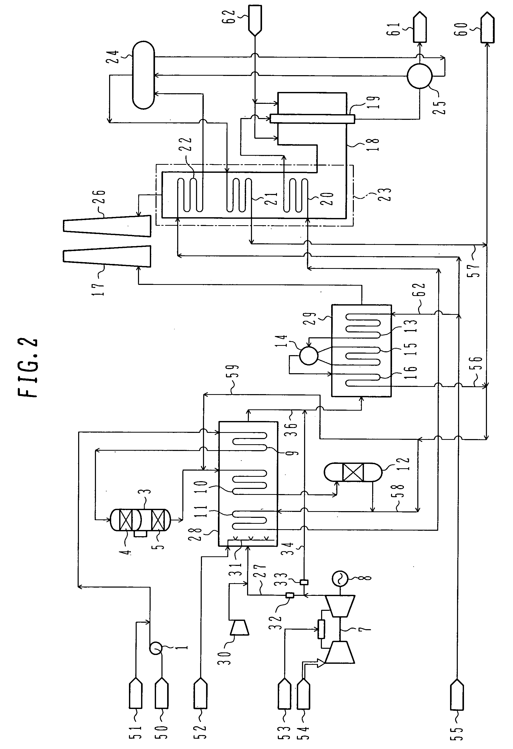
[0034] A second embodiment of the present invention will be described below with reference to FIG. 2. Note that a description of components common to those in the first embodiment is omitted here.

[0035] In this second embodiment, as shown in FIG. 2, the heat recovery exchanger 6 in the first embodiment is installed while it is divided into a first heat recovery exchanger 28 and a heat recovery steam generator 29 serving as a second heat recovery exchanger. The heat recovery exchanger 28 is used to preheat and heat the feedstocks, and the heat recovery steam generator 29 is used to generate steam. The flue gases of the gas turbine is distributed depending on the heat capacity of the heat recovery exchanger 28 by the damper 32 disposed in the GT flue gas duct 27 and a damper 33 disposed in a GT flue gas duct 34. The GT flue gas duct 27 branched to be extended to the heat recovery exchanger 28 includes the blower 30, and the heat recovery exchanger 28 includes the auxiliary burner 31....

third embodiment

[0039] A third embodiment of the present invention will be described below with reference to FIG. 3. Note that a description of components common to those in the first and second embodiments is omitted here.

[0040] In this third embodiment, the high-temperature flue gases of the gas turbine, which has bypassed the heat recovery exchanger 28, is directly introduced to the heat recovery steam generator 29, whereas the flue gases having passed the heat recovery exchanger 28 is introduced to the heat recovery steam generator 29 in its section (intermediate section) where the flue gases directly supplied from the gas turbine flow at temperature close to that of the flue gases introduced from the heat recovery exchanger 28. Stated another way, the second GT flue gas duct 36 connects the outlet of the heat recovery exchanger 28 to the intermediate section of a flue gas path in the heat recovery steam generator 29, and the third GT flue gas duct 34 connects an outlet of the gas turbine 7 (o...


PUM

PropertyMeasurementUnit
Flow rateaaaaaaaaaa

Abstract

A steam reforming system with high thermal efficiency, which can compensate for a reduction in the amount of steam generated in a reformer without increasing the reformer size and without limiting the degree of freedom in layout of the reformer and a gas turbine. A gas turbine and a heat recovery exchanger are additionally installed such that the gas turbine generates electric power, and flue gases of the gas turbine are employed to preheat feedstocks supplied to the reformer and to generate steam used for the pre-reforming stage. The heat recovery exchanger is disposed in a downstream channel for the flue gases (at 500-600° C.) of the gas turbine to perform heat exchange between the high-temperature flue gases of the gas turbine and the feedstocks supplied to the reformer, thereby increasing the temperature of the feedstocks to a level suitable for vaporization and desulfurization, and to a level suitable for the pre-reforming stage in a pre-reformer. Generation and superheating of steam required for the pre-reforming stage are performed by the remaining heat of the flue gases of the gas turbine.

Description

BACKGROUND OF THE INVENTION [0001] 1. Field of the Invention [0002] The present invention relates to a steam reforming system utilizing flue gases of a gas turbine, and more particularly to a steam reforming system equipped with a pre-reformer, which is used for a plant producing hydrogen, ammonia, methanol, etc. by using hydrocarbons with carbon numbers of C2 or more as feedstocks. [0003] 2. Description of the Related Art [0004] A reformer is employed in production processes for hydrogen, ammonia, methanol, etc. to produce, from hydrocarbons supplied as feedstocks, synthesis gases that serve in turn as feedstocks for producing those products. The hydrocarbons supplied as feedstocks are pressurized to a level of required pressure, and then subjected to preheating and desulfurization. After being mixed with steam, the feedstocks are heated to about 500° C. through heat exchange with flue gases leaving the reformer, and are introduced to a heated pipe of the reformer which is filled w...

Claims


Application Information

Patent Timeline
IPC IPC(8): F02C3/22F02C6/18
CPCF02C3/22F02C6/18C01B3/382C01B2203/0233C01B2203/84C01B2203/0894C01B2203/1258C01B2203/142C01B2203/0811Y02P20/10Y02P20/129
Inventor INUI, TAIJIKAWAGUCHI, TSUNEHISA
Owner MITSUBISHI POWER LTD
Why Eureka
Try Eureka