
Method & apparatus for multi-stage sputter deposition of uniform thickness layers

Active Publication Date: 2005-08-18
SEAGATE TECH LLC
View PDF19 Cites 15 Cited by
  • Summary
  • Abstract
  • Description
  • Claims
  • Application Information

AI Technical Summary

Benefits of technology

[0016] An advantage of the present invention is an improved cathode sputtering apparatus for forming uniform thickness layers of a selected material on substrate surfaces.

Problems solved by technology

Sputter deposition of relatively thick component layers of magnetic recording media, particularly the magnetically soft underlayer (SUL) of perpendicular media, in continuous, automatic fashion utilizing the above-described multi-chamber type sputtering apparatus is problematic for the following reasons:
(1) formation of relatively thick media component layers in a single process chamber by means of sputtering utilizing a single sputter deposition source requires a very costly high power, high deposition rate sputtering source to achieve the requisite layer thickness at substrate transport rates consistent with the high product throughput rates necessary for economic competitiveness; and
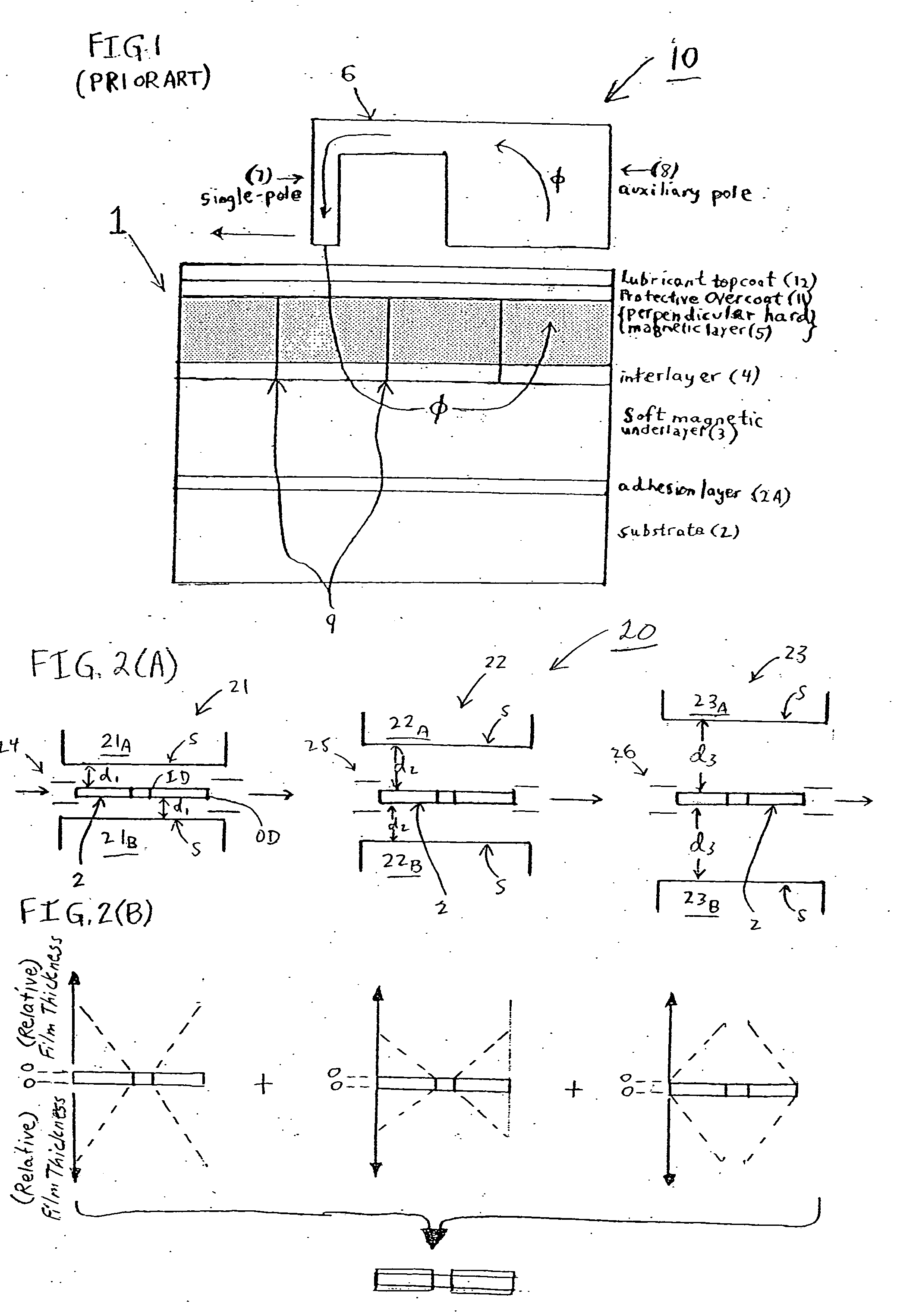
However, either of the above approaches entails a disadvantage / drawback in that formation of thick layers of the magnetically soft underlayer material on the shields surrounding the outer periphery (OD) of the annular disk-shaped substrates, eventually leads to flaking-off of the deposited SUL material, with possible deposition of the flaked-off SUL material on the substrate surfaces.
This in turn leads to layer defects and reduction in acceptable product yield.

Method used


Image

  • Method & apparatus for multi-stage sputter deposition of uniform thickness layers
  • Method & apparatus for multi-stage sputter deposition of uniform thickness layers
  • Method & apparatus for multi-stage sputter deposition of uniform thickness layers

Examples


Embodiment Construction

[0051] The present invention addresses and solves quality, yield, throughput, and manufacturing cost-effectiveness problems associated with processing techniques for automated, continuous manufacture of a variety of products requiring deposition of a plurality of thin film component layers on a substrate, wherein at least one of the thin film layers is relatively thicker. The invention, therefore, has particular utility in the continuous, automated manufacture of high areal recording density perpendicular magnetic recording media, e.g., in hard disk form, which perpendicular media require formation of a relatively thick soft magnetic underlayer (SUL), as described in detail supra. Further, the invention advantageously facilitates high product throughput, continuous, automated manufacture of such perpendicular media in hard disk form, while maintaining fill compatibility with all aspects and requirements of automated manufacturing technology and methodology.

[0052] More specifically,...


PUM

PropertyMeasurementUnit
Lengthaaaaaaaaaa
Thicknessaaaaaaaaaa
Diameteraaaaaaaaaa

Abstract

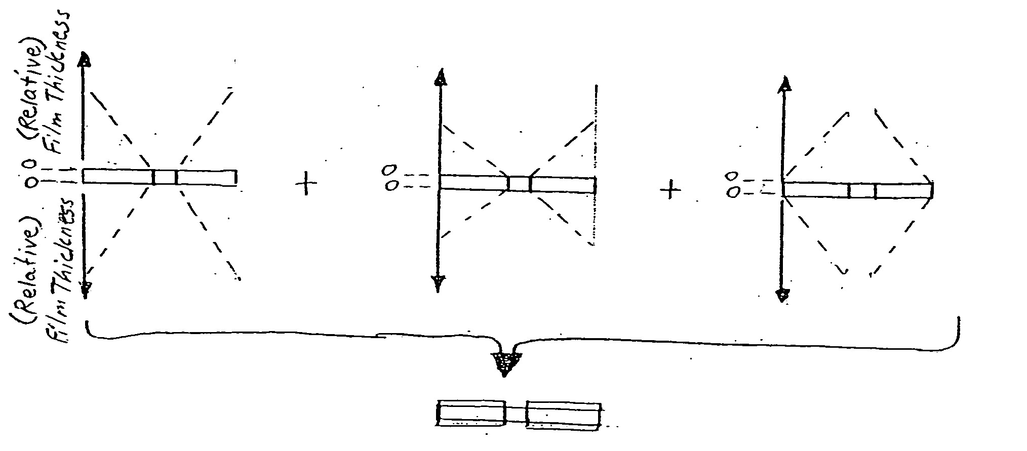
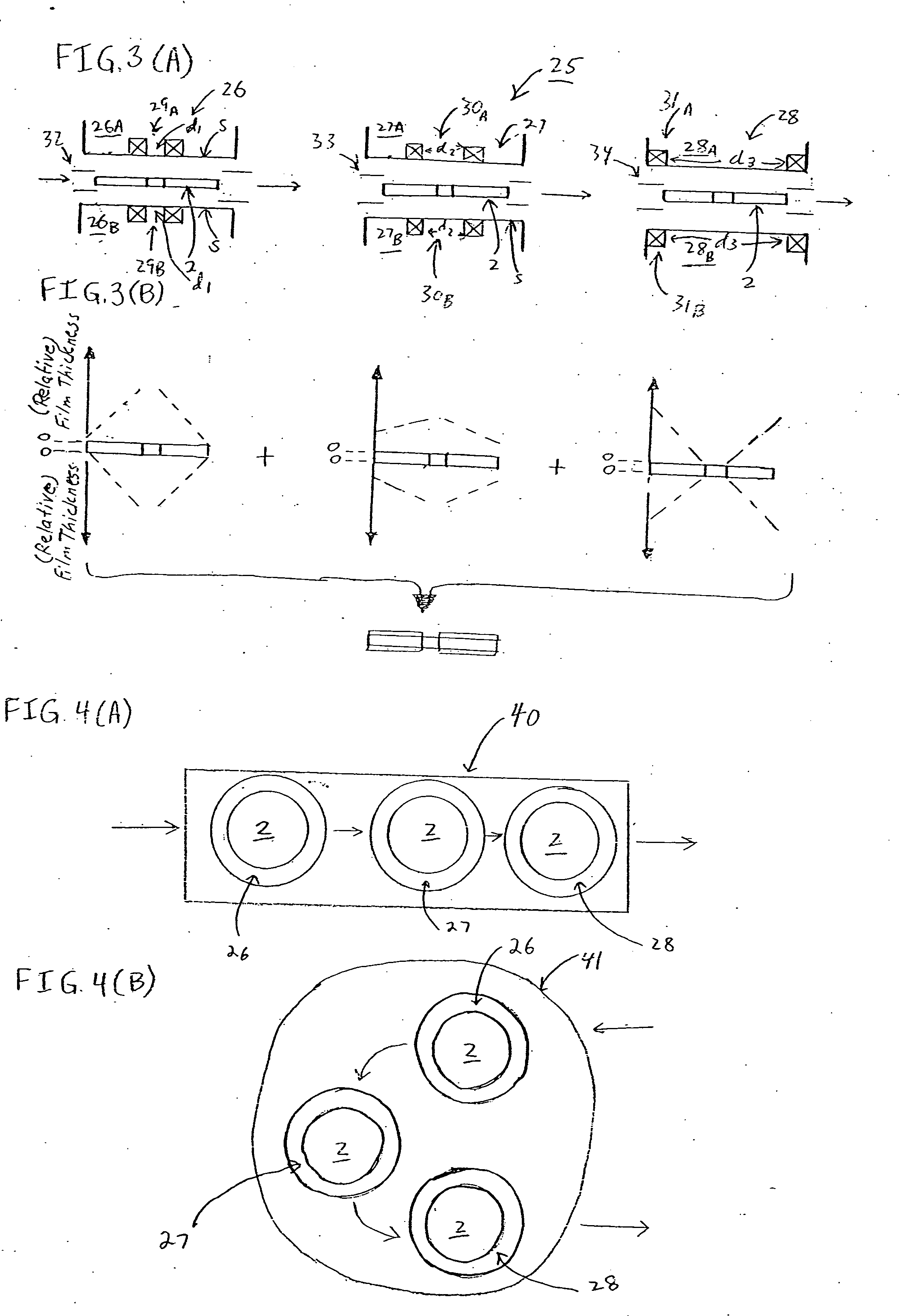
A method of forming a uniform thickness layer of a selected material on a surface of a substrate comprises steps of: (a) providing a multi-stage cathode sputtering apparatus comprising a group of spaced-apart cathode / target assemblies and a means for transporting at least one substrate / workpiece past each cathode / target assembly, each cathode / target assembly comprising a sputtering surface oriented substantially parallel to the first surface of the substrate during transport past the group of cathode / target assemblies, the group of cathode / target assemblies adapted for providing different angular sputtered film thickness profiles; and (b) transporting the substrate past each cathode / target assembly while providing different sputtered film thickness profiles from at least some of the cathode / target assemblies, such that a plurality of sub-layers is deposited on the surface of the substrate / workpiece which collectively form a uniform thickness layer of the selected material.

Description

FIELD OF THE INVENTION [0001] The present invention relates to a method and apparatus for forming uniform thickness layers of a selected material by means of plural sputter deposition stages. The invention has particular utility in the automated manufacture of high performance perpendicular magnetic recording media, e.g., hard disks, at high product throughput rates. BACKGROUND OF THE INVENTION [0002] Magnetic media are widely used in various applications, particularly in the computer industry, and efforts are continually made with the aim of increasing the areal recording density, i.e., bit density, of the magnetic media. In this regard, so-called “perpendicular” recording media have been found to be superior to the more conventional “longitudinal” media in achieving very high bit densities. In perpendicular magnetic recording media, residual magnetization is formed in a direction perpendicular to the surface of the magnetic medium, typically comprised of a layer of a magnetically ...

Claims


Application Information

Patent Timeline
IPC IPC(8): C23C14/16C23C14/18C23C14/20C23C14/32C23C14/35C23C14/56G11B5/851
CPCC23C14/165C23C14/185G11B5/851C23C14/352C23C14/568C23C14/205
Inventor RANJAN, RAJIV YADAVREITER, JEFFREY SHANENOLAN, THOMAS PATRICK
Owner SEAGATE TECH LLC
Learn More