Field emission device

a field emission and field technology, applied in the manufacture of electric discharge tubes/lamps, instruments, discharge tubes luminescnet screens, etc., can solve the problems of small color gamut, many light losses and inherent complexity of amcld devices, and non-emisive amcld devices, etc., to achieve good stability

Inactive Publication Date: 2005-08-18
UNIV COURT OF THE UNIV OF DUNDEE
View PDF10 Cites 38 Cited by
  • Summary
  • Abstract
  • Description
  • Claims
  • Application Information

AI Technical Summary

Benefits of technology

[0012] In one embodiment, the present invention now provides a series of polymers or copolymers doped with fluorescent dyes suitable for use in electro-luminescent devices. Thes...

Problems solved by technology

AMCLD devices are non-emissive and require complex lithography.
However, there are many light losses and inherent complexity in AMCLD devices because of the non-linear nature of liquid crystal materials.
These result in a display that is less bright than a CRT, with a smaller color gamut and poorer viewing angle and contrast.
Also, due to the non-emissive nature of the display, inefficient use of input electrical power is made, often with well over 70% of the energy being lost as non-useful energy.
Unfortunately, the extreme complication in fabrication has limited the use of this technology.
Additionally, crystal silic...

Method used


Image

  • Field emission device
  • Field emission device
  • Field emission device

Examples


first embodiment

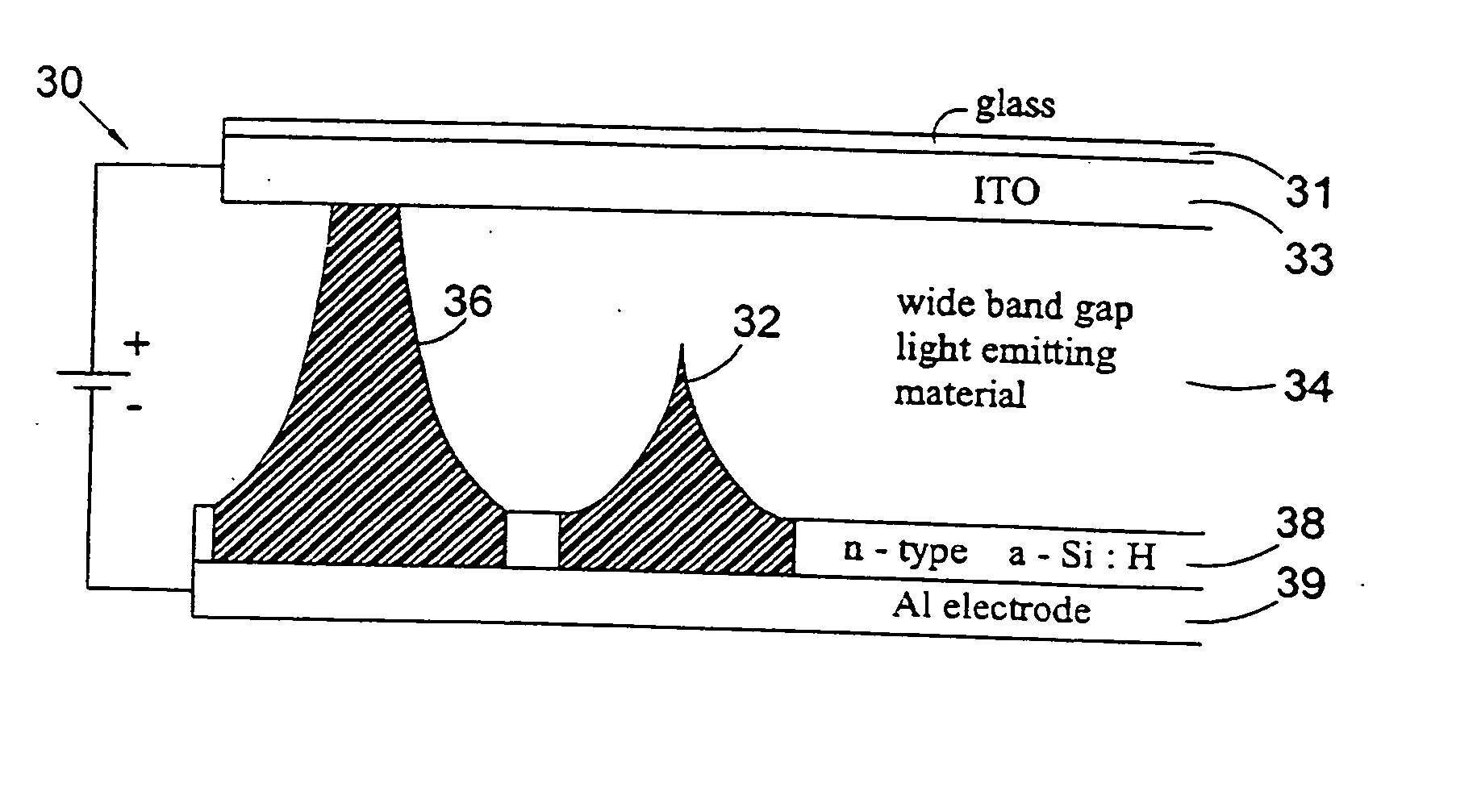
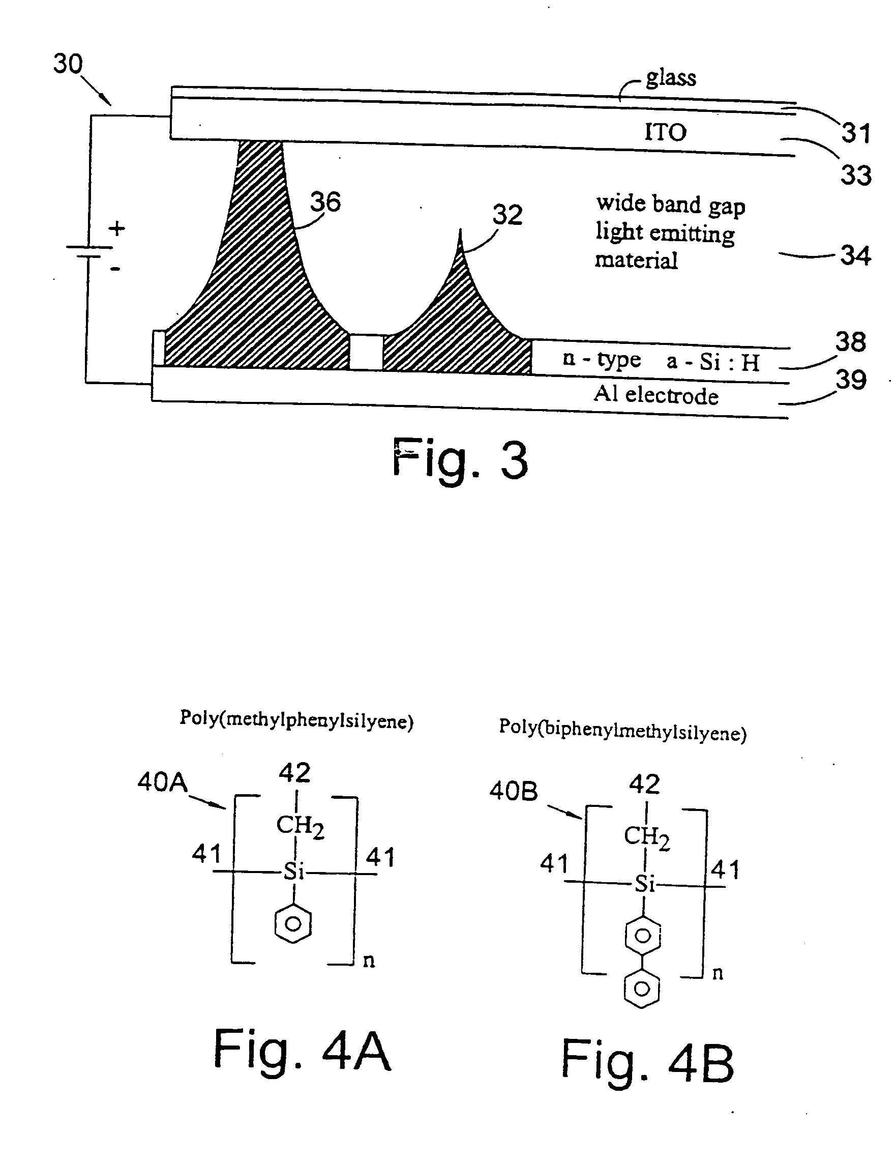
[0060] According to the present invention there is provided an electro-luminescent and / or photo-luminescent material having a fluorescent material chemically attached thereto, the electro-luminescent and / or photo-luminescent material comprising a polymeric material comprising an amorphous polysilyene doped with at least one fluorescent dye chemically attached to the polymeric material.

[0061] It should be understood that the polymeric material may be a polymer, and it should be further understood that by polymer is included a homopolymer or copolymer.

[0062] Preferably the polymer(s) or copolymer(s) may be a high temperature polymer.

[0063] Alternatively the polymer(s) or copolymer(s) may be a pyrazol based organic material.

second embodiment

[0064] According to the present invention there is provided a fluorescent dye doped material comprising polymer based micro-spheres formed of a first polymeric material doped with at least one fluorescent dye, wherein the micro-spheres of the first polymeric material are embedded within a polymer based host, and wherein the polymer material based host is formed of a second polymeric material.

[0065] Preferably the first polymeric material has a higher refractive index than the second polymeric material.

[0066] Conveniently the first polymeric material has a higher, or alternatively lower softening temperature than the second polymeric material.

[0067] Preferably the first polymeric material comprises polystyrene doped with at least one fluorescent dye.

[0068] Preferably the second polymeric material comprises an ethylene-vinyl-acetate based polymer. [0069] where A is a substituent selected from the group consisting of substituted or unsubstituted aromatic or heteroaromatic rings and ...

fifth embodiment

[0074] According to the present invention there is provided a fluorescent dye doped material comprising polymer based micro-spheres formed of a first polymeric material doped with at least one fluorescent dye, wherein the first polymeric material micro-spheres are embedded within a polymer based host comprising a second polymeric material, the first polymeric material having a higher softening temperature than the second polymeric material.

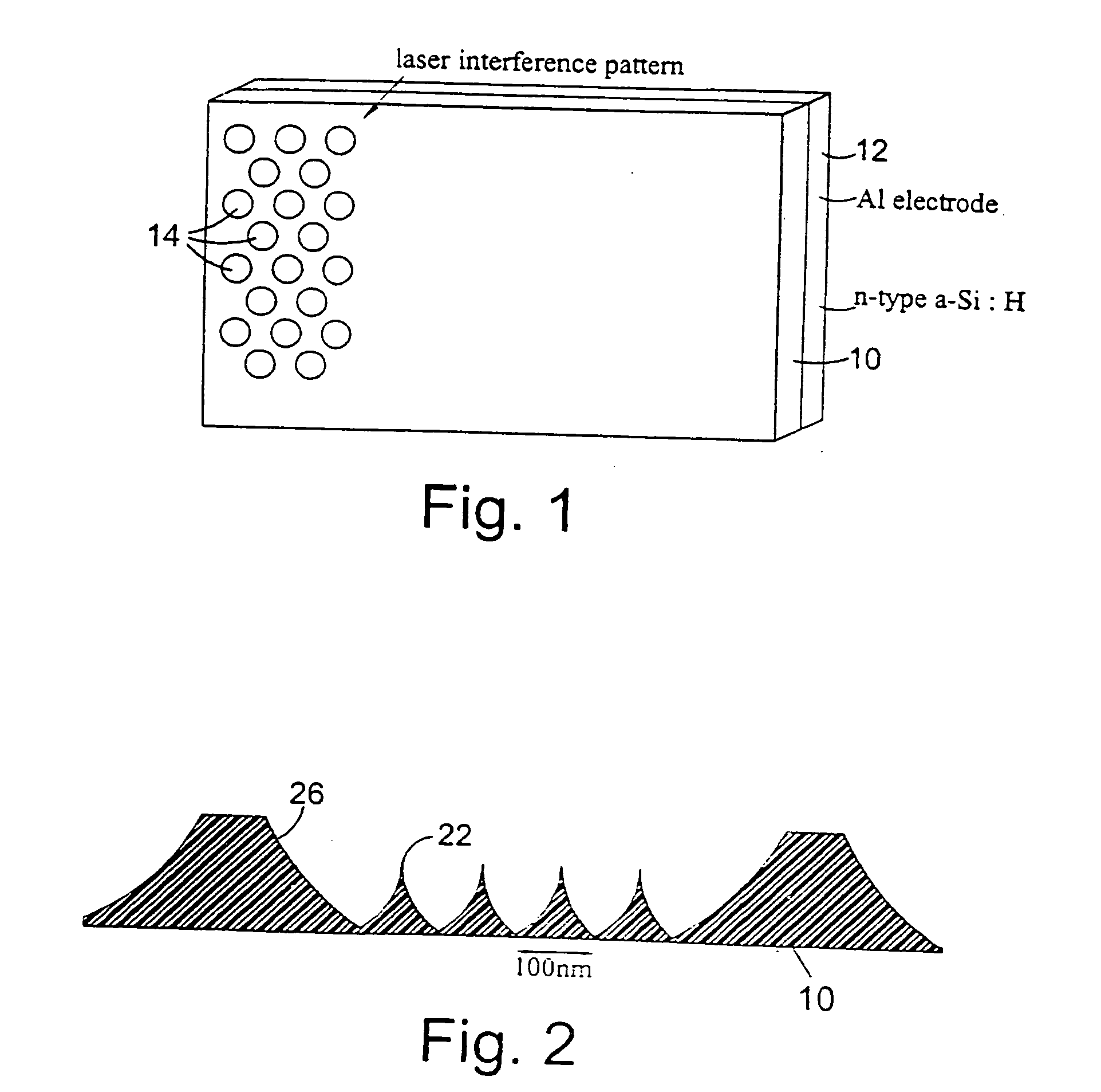
[0075] Preferably a diameter of the micro-spheres is substantially the same as a wavelength of fluorescent light emitted by the fluorescent dye molecules resulting in optical resonance effects occurring within the micro-spheres thereby enhancing the intensity of the fluorescent light.

[0076] According to a second aspect of the present invention there is provided a field emission device comprising a field emission means and an electro-luminescent and / or photo-luminescent material doped with at least one fluorescent dye, wherein the electro-luminesc...


PUM


Abstract

A field emission device having improved properties and which finds use in display devices, such as a flat panel displays. Known devices and displays suffer from problems such as complexity of fabrication and limited color gamut. The present device provides a field emission backplate which is made from a substantially semiconductor based material and has a plurality of grown tips. The device also includes at least one electro-luminescent or photo-luminescent material having a fluorescent material such as a fluorescent dye doped material chemically attached thereto.

Description

CROSS-REFERENCE TO RELATED APPLICATIONS [0001] This application is a continuation of International Application PCT / GB03 / 02634 filed Jun. 19, 2003, the entire content of which is expressly incorporated herein by reference thereto.FIELD OF INVENTION [0002] The present invention relates to an improved field emission device including a fluorescent dye doped material and to the use of such fluorescent dye doped materials in a field emission device. The field emission device may particularly, though not exclusively, be used in a display device such as a so-called “flat panel” display. The invention also relates to a novel hybrid display device. BACKGROUND [0003] Flat panel displays are of immense importance in electronics. In current developments, Active Matrix Liquid Crystal Displays (AMCLD) are beginning to challenge the dominance of Cathode Ray Tube (CRT) technology. AMCLD devices are non-emissive and require complex lithography. Filters and matching spectral backlights are required to...

Claims


Application Information

Patent Timeline
IPC IPC(8): H01J1/304H01J9/02H01J1/62H01L51/52H05B44/00
CPCG02F2001/133625H01J1/3044H01L51/5221H01J2201/30446H01J2201/30407G02F1/133625H10K50/822H05B33/10H05B33/14H05B33/26H05B45/60
Inventor ROSE, MERVYN JOHNSILVA, RAVISHANNON, JOHNHAJTO, JANOS PETER
Owner UNIV COURT OF THE UNIV OF DUNDEE
Why Eureka
Try Eureka