Hotspot spray cooling

a technology of spray cooling and thermal management system, which is applied in the direction of basic electric elements, semiconductor devices, lighting and heating apparatus, etc., can solve the problems of increasing the cost of cooling system, so as to achieve more repeatability and improve efficiency

Inactive Publication Date: 2005-08-25
ISOTHERMAL SYST RES
View PDF32 Cites 37 Cited by
  • Summary
  • Abstract
  • Description
  • Claims
  • Application Information

AI Technical Summary

Benefits of technology

[0021] Another embodiment of the present invention uses a liquid-vapor separator for separating liquid and vapor from the exit stream of a spray module prior to condensing the vapor. The res

Problems solved by technology

As air cooling heat sinks continue to be pushed to new performance levels, so has their cost, complexity, and weight.
For some time, liquid cooling solutions have been developed and tested, but other than specialty applications they have yet to gain widespread commercial adoption.
This non-uniform heat flux distribution poses a significant challenge to the cooling system as it is desirable to keep the entire chip at nearly the same operating temperature.
Cooling systems that rely on heat spreading may not provide this ability as they rely on conduction spreading, resulting in significant temperature gradients across the chip.
Although this method improves the efficiency of the syst

Method used


Image

  • Hotspot spray cooling
  • Hotspot spray cooling
  • Hotspot spray cooling

Examples


Embodiment Construction

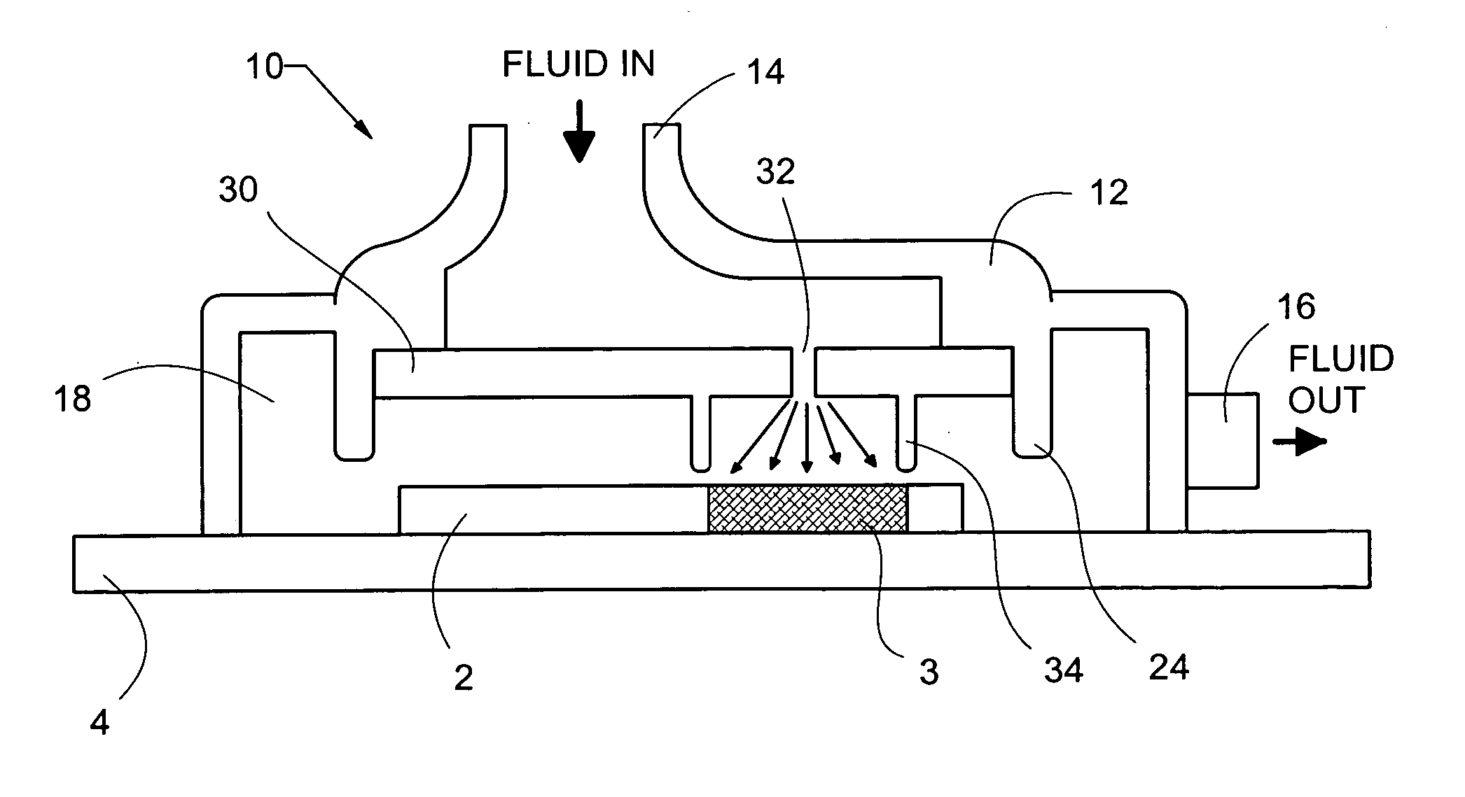
[0038] Many of the fastening, connection, manufacturing and other means and components utilized in this invention are widely known and used in the field of the invention are described, and their exact nature or type is not necessary for a person of ordinary skill in the art or science to understand the invention; therefore they will not be discussed in detail.

[0039] Applicant hereby incorporates by reference the following U.S. patents: U.S. Pat. No. 5,220,804 for a high heat flux evaporative cooling system; and U.S. Pat. No. 5,860,602 and U.S. Pat. No. 6,016,969, each for a laminated array of pressure swirl atomizers, and U.S. Pat. No. 6,108,201 for a fluid control apparatus and method for spray cooling and U.S. patent application Ser. No. 10 / 281,391 for an actuated atomizer. Although a laminated pressure swirl atomizer array is hereby incorporated by reference and shown in the accompanying drawings, the present invention is not limited to such an apparatus, in fact, many dispensin...


PUM


Abstract

The present invention is a spray cooling thermal management device that cools an electronic component creating a varying amount of heat across its surfaces. Liquid coolant is dispensed upon the surface of the component. In areas of the chip that generate large heat fluxes, typically referred to as the core, the liquid coolant is dispensed as a continuous atomized droplet pattern. The atomized pattern creates a high heat flux evaporative cooling thin-film over the one or more core areas. Rather than optimize the atomized pattern and flow based upon complete thin-film vaporization, the present invention optimizes the atomized pattern for maximum heat removal rates. Any excess, non-vaporized, fluid flowing outward from the hotspot is used to cool the lower heat flux (non-core) areas of the component through the creation of a thick coolant film thereon.

Description

STATEMENT REGARDING FEDERALLY SPONSORED RESEARCH OR DEVELOPMENT [0001] This invention was made with Government support under contract #F33615-03-M-2316 awarded by the Air Force Research Laboratory. The Government has certain rights in this invention.CROSS REFERENCE TO RELATED APPLICATIONS [0002] None BACKGROUND [0003] 1. Field of the Invention [0004] The present invention relates generally to spray cooling thermal management systems and more specifically it relates to a spray cooling system that provides high heat flux evaporative cooling of electronic component hotspots. [0005] 2. Description of the Related Art [0006] Liquid cooling is well known in the art of cooling electronics. As air cooling heat sinks continue to be pushed to new performance levels, so has their cost, complexity, and weight. For some time, liquid cooling solutions have been developed and tested, but other than specialty applications they have yet to gain widespread commercial adoption. As computer power consum...

Claims


Application Information

Patent Timeline
IPC IPC(8): F28D15/02F28F7/00H01L23/473
CPCF28D15/0266H01L23/4735H01L2924/0002H01L2924/00
Inventor TILTON, CHARLES L.TILTON, DONALD E.WEIR, THOMAS D.CADER, TAHIRKNIGHT, PAUL A.
Owner ISOTHERMAL SYST RES
Why Eureka
Try Eureka