Sampling interface system for in-vivo estimation of tissue analyte concentration

a tissue analyte and sampling interface technology, applied in the field of near-infrared spectroscopy-based biological parameter measurement, can solve the problems of current monitoring techniques that discourage regular use, diabetes is a leading cause of death and disability worldwide, and abnormal production and use of insulin, so as to improve the accuracy and precision of fluid delivery, improve the performance of optical analyzer, and minimize sampling errors

Inactive Publication Date: 2005-08-25
SENSYS MEDICAL
View PDF98 Cites 106 Cited by
  • Summary
  • Abstract
  • Description
  • Claims
  • Application Information

AI Technical Summary

Benefits of technology

[0046] A coupling medium such as an optical coupling fluid, placed on the surface of tissue at a tissue measurement site, is used to enhance performance of an optical analyzer coupled to the tissue measurement site. Means of assuring that the same tissue sample volume is repeatably sampled are presente

Problems solved by technology

Diabetes is a chronic disease that results in abnormal production and use of insulin, a hormone that facilitates glucose uptake into cells.
Diabetes is a leading cause of death and disability worldwide.
However, current monitoring techniques discourage regular use due to the inconvenient and painful nature of drawing blood through the skin prior to analysis (The Diabetes Control and Complication Trial Research Group, The effect of intensive treatment of diabetes on the development and progression of long-term complications of insulin-dependent diabetes mellitus, supra.
Unfortunately, recent reports indicate that even periodic measurement of glucose concentration by individuals with diabetes, (e.g. seven times per day) is insufficient to detect important glucose concentration fluctuations and properly manage the disease.
There

Method used


Image

  • Sampling interface system for in-vivo estimation of tissue analyte concentration
  • Sampling interface system for in-vivo estimation of tissue analyte concentration
  • Sampling interface system for in-vivo estimation of tissue analyte concentration

Examples


example i

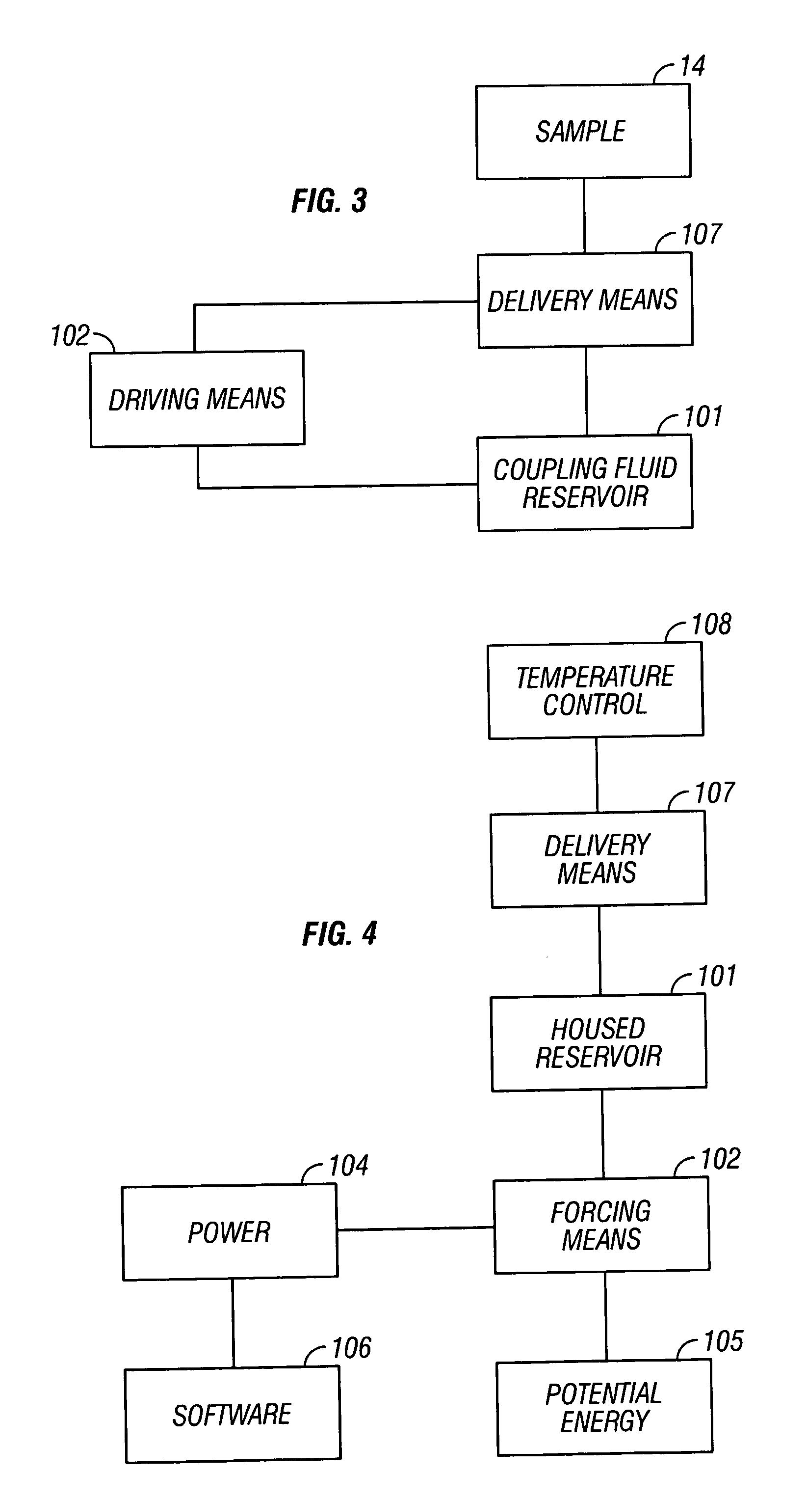
[0119] Referring now to FIG. 3, a block diagram of an automated coupling fluid delivery system is provided. A coupling fluid is held in a reservoir 101. This reservoir contains the fluid in a package that allows for ready transport, protection from contaminants, and on-time delivery. An example reservoir is a syringe. Fluid is forced from the reservoir by driving means 102, such as a plunger. In this example a linear drive motor is used to move the plunger 102 into the syringe 101 and force coupling fluid through tubing 107 to the sample site 14.

[0120] Referring now to FIG. 4, optional power supplies 104 are used for powering the driving means 102 and include gravity and / or manual, alternating current, or direct current power. Often, the driving forces required tax a power budget. An optional potential energy assist 105 is provided to minimize auxiliary power requirements. Examples of a potential energy source 105 include a coiled spring or compressed gas, infra.

[0121] Optional so...

example ii

[0122] In a second example of the invention, coupling fluid is delivered through tubing to a sample site. After delivery the coupling fluid is backed off from the end of the tubing exit, such as by capillary action or by reversing a pushing force into a pulling force. For example, a motor pushing the fluid is reversed and the fluid is pulled back a distance into the tubing. A sensor is optionally placed across the tubing to determine the position of the meniscus of the coupling fluid in the tubing. For example, a light source, such as a light emitting diode, shines through the tubing and is sensed by a detector. As first air and then coupling fluid is moved past the sensor in the tubing, a change in light intensity is indicative of the meniscus and hence the position of the coupling fluid in the tubing. The dead volume of tubing past the detector is readily calculated. The driving means 102, such as a stepper motor, are then used to deliver the dead volume of coupling fluid plus the...

example iii

[0123] In a third example of the invention, a series of optical readings are collected by the analyzer. As the sample probe is brought into proximity to the sample site 14, the near-infrared reading changes. Features of the signal are indicative of the distance between the tip of the sample probe and the sample site. For example, the collected intensity at wavelengths of high absorbance decrease toward zero as the tip of the sample probe approaches a tissue sample. An example of a high absorbance feature is water at or about 1450 nm, 1900 nm, and / or 2600 nm. Correlation between intensity readings at one or more wavelengths and distance between the tip of the sample probe are used to provide feedback to the user or preferably to a z-axis moveable sample probe. The feedback allows the controller to move the sample probe relative to the tissue sample site. This allows, for example, controlling the probe to make contact with the sample, for the sample probe to be backed off from the sam...


PUM


Abstract

Sampling is controlled to enhance analyte concentration estimation derived from noninvasive sampling. Means of assuring that the same tissue sample volume is repeatably sampled are presented, thus minimizing sampling errors due to mechanical tissue distortion, specular reflectance, and probe placement. In a first embodiment of the invention, sampling is controlled using automated delivery of a coupling fluid to a region between a tip of a sample probe and a tissue measurement site in a manner requiring minimal user interaction. In a second embodiment of the invention, sampling is controlled by controlling temperature variations, preferably with a coupling fluid, at a region about the tip of a sample probe and a sample site. In a third embodiment, sampling is procedurally controlled via timing and location of coupling fluid delivery to a sample site.

Description

CROSS REFERENCES TO RELATED APPLICATIONS [0001] This application claims priority from: [0002] U.S. provisional patent application Ser. No. 60 / 536,197, filed Jan. 12, 2004; [0003] U.S. provisional patent application Ser. No. 60 / 534,834, filed Jan. 6, 2004; [0004] U.S. provisional patent application Ser. No. 60 / 566,568, filed Apr. 28, 2004; [0005] U.S. patent application Ser. No. 10 / 472,856, filed Mar. 7, 2003, which claims priority from PCT application no. PCT / US03 / 07065, filed Mar. 7, 2003, which claims benefit of U.S. provisional patent application Ser. No. 60 / 362,885, filed Mar. 8, 2002; and [0006] U.S. patent application Ser. No. 10 / 170,921 filed Jun. 12, 2002, which claims benefit of U.S. patent application Ser. No. 09 / 563,782, now U.S. Pat. No. 6,415,167, which issued Jul. 2, 2002 each of which is incorporated herein in its entirety by this reference thereto. BACKGROUND OF THE INVENTION [0007] 1. Field of the Invention [0008] This invention relates generally to the noninvasive ...

Claims


Application Information

Patent Timeline
IPC IPC(8): A61B5/00G01N21/35
CPCA61B5/0075A61B5/14532G01N21/359A61B2562/146A61B5/1455
Inventor BLANK, THOMAS B.ACOSTA, GEORGE M.MONFRE, STEPHEN L.ABUL-HAJ, ROXANNE E.HAZEN, KEVIN H.BROWN, SEDARRICHIE, BENJAMIN L. JR.HENDERSON, JAMES R.ELLIOTT, BARRY C.HOPE, JOSH
Owner SENSYS MEDICAL
Why Eureka
Try Eureka