
Organic polariton laser

Active Publication Date: 2005-09-08
THE TRUSTEES FOR PRINCETON UNIV
View PDF13 Cites 15 Cited by
  • Summary
  • Abstract
  • Description
  • Claims
  • Application Information

AI Technical Summary

Problems solved by technology

The almost complete lack of change in these parameters (including slope efficiency) is due to the isolated, quantum nature of the excited state in organic thin films.
These molecular states are largely isolated from those of the environment, leading to lack of sharing of electrons in broad energy bands as occurs in inorganic semiconductors.
It is becoming increasingly apparent that the conventional techniques applied to achieving electrically induced laser emission in inorganic semiconductors, such as the use of an intensely pumped double heterostructure, may not be suited for the successfully generation of the laser emission in organic semiconductors.
In organic materials, losses related to thin film resistance, polaron quenching and absorption, and singlet exciton annihilation may ultimately prohibit an organic thin film from reaching the lasing threshold by conventional approaches.

Method used


Image

  • Organic polariton laser
  • Organic polariton laser
  • Organic polariton laser

Examples


example 1

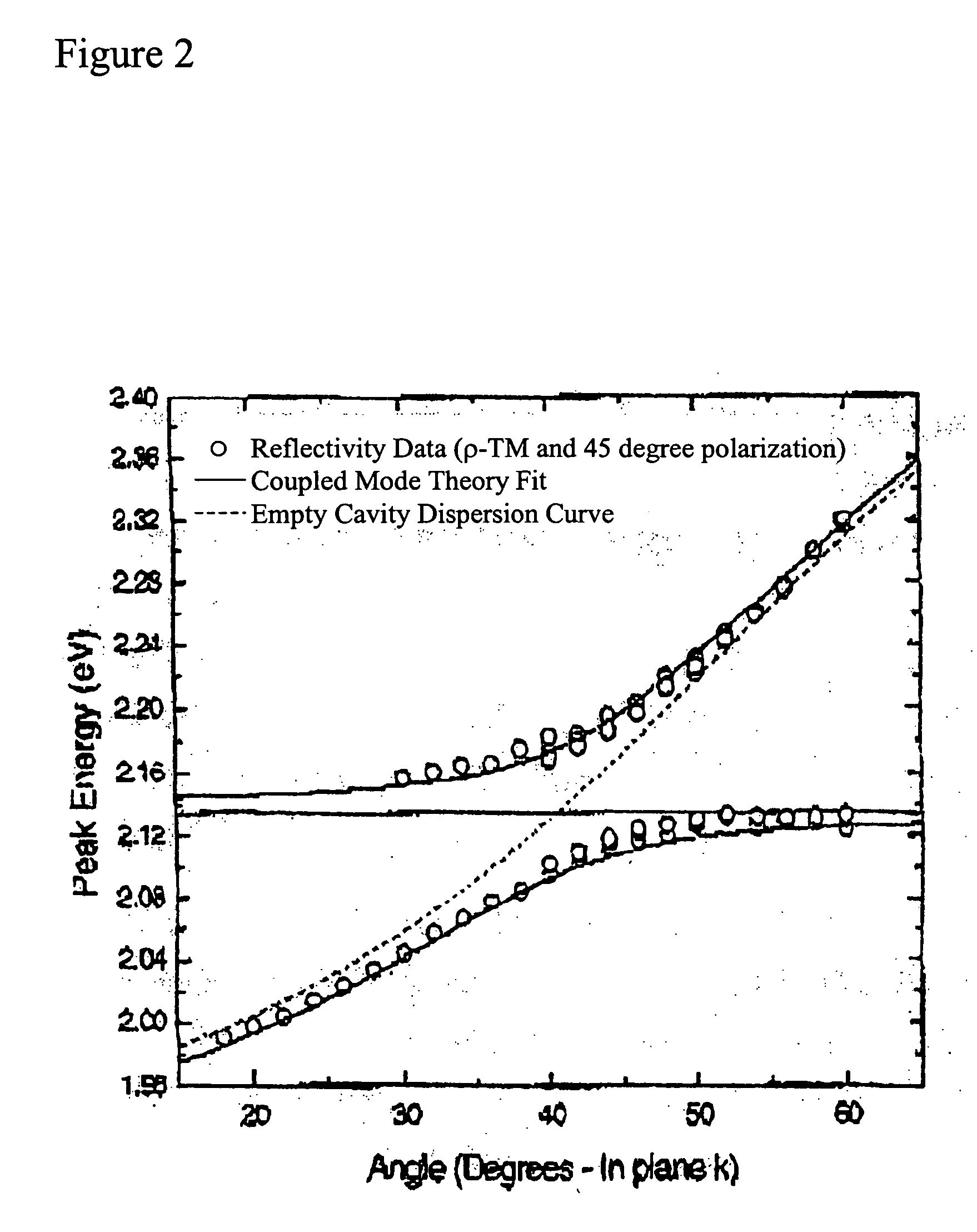
[0043] An OMCs completely filled with the thermally evaporated polycrystalline material 3,4,7,8 napthalenetetracarboxylic dianhydride (NTCDA) was prepared and exhibited strong coupling and the hybridization of excitons arising from separate vibronic transitions characteristic of this molecular species. Distributed Bragg reflectors (DBR) consisting of 8 pairs of quarter wavelength thick SiO2 and SiNx layers were deposited on quartz substrates using plasma enhanced chemical vapor deposition, yielding a peak reflectivity of 90%. A polycrystalline film of NTCDA was deposited onto the DBR mirror by sublimation at 10−7 Torr, forming a cavity between the DBR and a 200 nm Al cap deposited onto the NTCDA surface by thermal evaporation. The dispersion relation of each OMC was determined by using angularly resolved reflection spectroscopy, measuring sample reflectivity as a function of excitation wavelength and angle (R. Houdre, C. Weisbuch, R. P. Stanley, U. Oesterle, P. Pellandini, and M. Il...

example 2

[0047] Microcavities with 40 m and 60 nm thick active layers of NTCDA were fabricated as in Example 1. In general, Ω varies as (αL)1 / 2, where α and L are the absorption coefficient and thickness of the NTCDA layer respectively (C. Weisbuch, M. Nishioka, A. Ishikawa, and Y. Arakawa, Phys. Rev. Lett. 69, 3314 (1992)). Reflectivity spectra collected at selected angles for these microcavities are depicted in FIG. 7. Aside from the features arising from coupling between the cavity mode and the 0-0 transition of NTCDA, a third feature is also observed at higher energy, consistent with coupling to the 0-1 transition of NTCDA, yielding the dispersion relations in FIG. 8. Anti-crossing between branches is observed, and both the middle and upper branches asymptotically approach their respective uncoupled exciton energies at low angle. The middle branch of the dispersion relation for both thicknesses becomes clearly visible at θ>20°, whereas the top branch is observed at θ>35°, where this bran...


PUM


Abstract

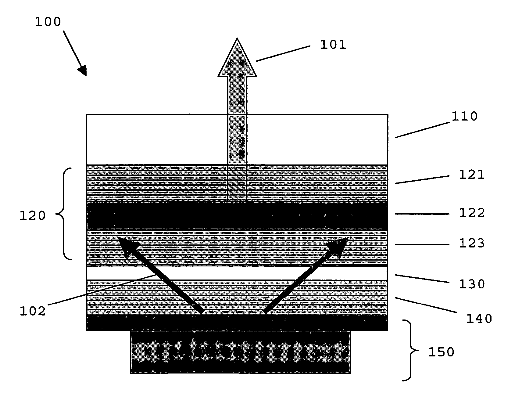
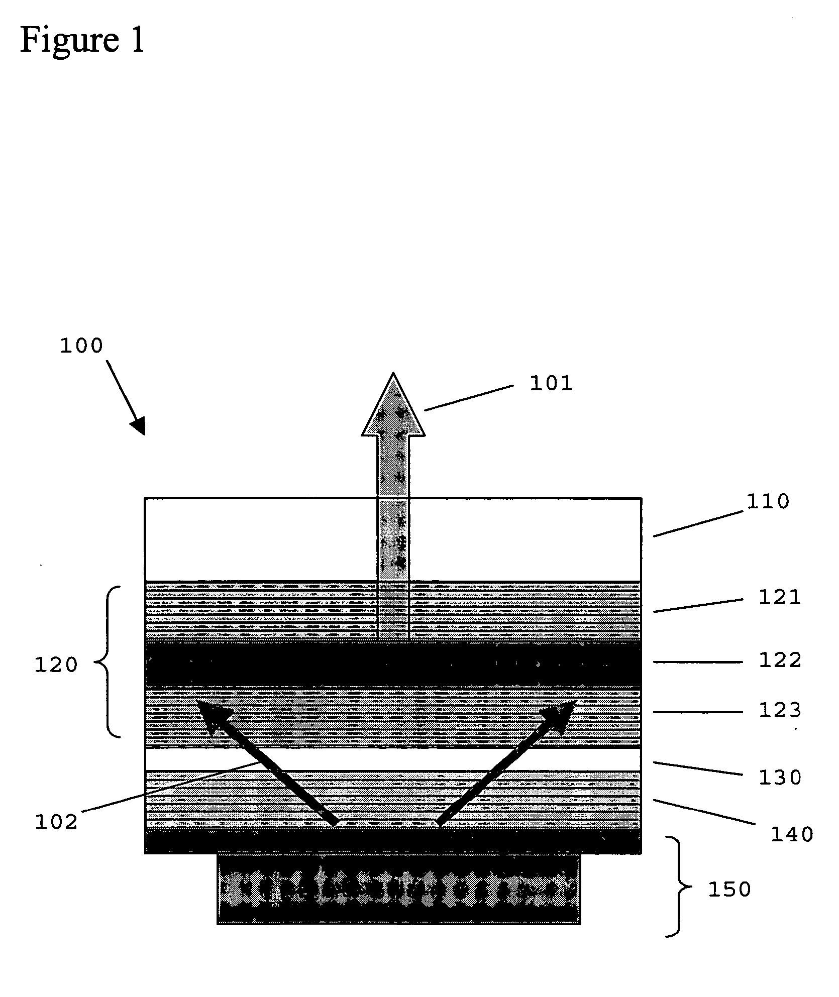
The present invention relates to organic lasers. More specifically, the present invention is directed to an organic laser that provides a self-stimulated source of coherent radiation originating from organic microcavity polaritons. The organic polariton laser of the present invention comprises a substrate, a resonant microcavity comprising an organic polariton emission layer; and an optical pump. In preferred embodiments the optical pump is a microcavity OLED allowing for the fabrication of a self-contained or integrated device.

Description

RELATED APPLICATIONS [0001] This application is a continuation-in-part of pending application Ser. No. 10 / 793,968, filed on Mar. 5, 2004, which is incorporated herein by reference in its entirety.FIELD OF THE INVENTION [0002] The present invention relates to organic lasers. More specifically, the present invention is directed to an organic laser that provides a self-stimulated source of coherent radiation originating from organic microcavity polaritons. BACKGROUND [0003] The past fifteen years have seen an explosive growth of research interest in the study and application of organic materials as the active media in organic opto-electronic devices. Today, this work has culminated with organic light emitting devices (OLEDs), and specifically phosphorescent OLEDs. Opto-electronic devices that make use of organic materials are becoming increasingly desirable for a number of reasons. Many of the materials used to make such devices are relatively inexpensive, so organic opto-electronic de...

Claims


Application Information

Patent Timeline
IPC IPC(8): H01S3/14H01S3/16H01S3/30H01S5/04H01S5/183H01S5/36
CPCH01S3/0933H01S3/168H01S3/30H01S5/36H01S5/041H01S5/18305H01S5/18369H01S5/026
Inventor FORREST, STEPHEN R.HOLMES, RUSSELL
Owner THE TRUSTEES FOR PRINCETON UNIV
Learn More