High temperature joints for dissimilar materials

a technology of dissimilar materials and joints, applied in the direction of pipe joints, pipe connection arrangements, mechanical equipment, etc., can solve the problems of high coefficient of thermal expansion, limited strength at high operational temperatures of membranes, and excessive so as to improve the resistance to fluid leakage through joints and high strength

Inactive Publication Date: 2005-09-15
BP CORP NORTH AMERICA INC
View PDF26 Cites 14 Cited by
  • Summary
  • Abstract
  • Description
  • Claims
  • Application Information

AI Technical Summary

Benefits of technology

[0019] More particularly, in one aspect this invention provides a joint which comprises a girdle of a metallic material capable of undergoing deformation without rupture that is disposed between and contiguous with tapered mating surfaces of a first rigid member and a second rigid member, wherein differential pressure across the joint provides compressive force upon the girdle through the mating surfaces. Resistance to fluid leakage through the joint is thereby improved. Such joints resistant to fluid leakage advantageously are used for membrane reactors converting, for example, natural gas to synthesis gas by controlled partial oxidation and reforming reactions, and when desired subsequent conversion of the synthesis gas to added-value products, for example, by a water-gas shift process. Generally, in joints according to the invention the first rigid member comprises a nonmetallic material selected from the group consisting of glass, porcelain, and ceramic, and the second rigid member comprises a high strength metallic material capable of being welded, such as high-chromium ferritic steels and iron-chromium-aluminum alloys.

Problems solved by technology

A persistent problem in design, operation and maintenance of such apparatus is that ceramic and rigid metal members typically exhibit different coefficients of thermal expansion, which can cause excessive fluid leakage through the joint, even fracture of the ceramic members, due to mechanical stresses during heating and cooling of the reactors.
A major obstacle in developing viable joints is the unique mechanical properties of ceramic materials, e.g., high coefficients of thermal expansion and limited strength at the high operational temperatures of the membranes.
Both factors prohibit the use of common fixed joining techniques such as welding or brazing.
As mentioned above, it is difficult to make reliable ceramic-to-metal seals in the first instance.
This sealing problem becomes particularly troublesome when many tubular ceramic elements are to be attached to a tube-sheet.
Furthermore, such assembly only allows for the testing of the ceramic-to-metal seal after assembly.

Method used


Image

  • High temperature joints for dissimilar materials
  • High temperature joints for dissimilar materials
  • High temperature joints for dissimilar materials

Examples


example 1

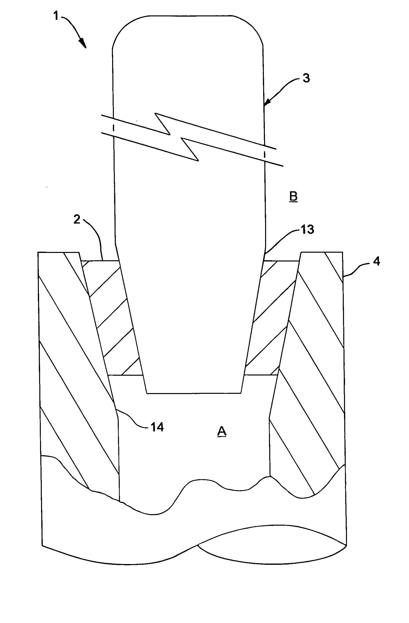
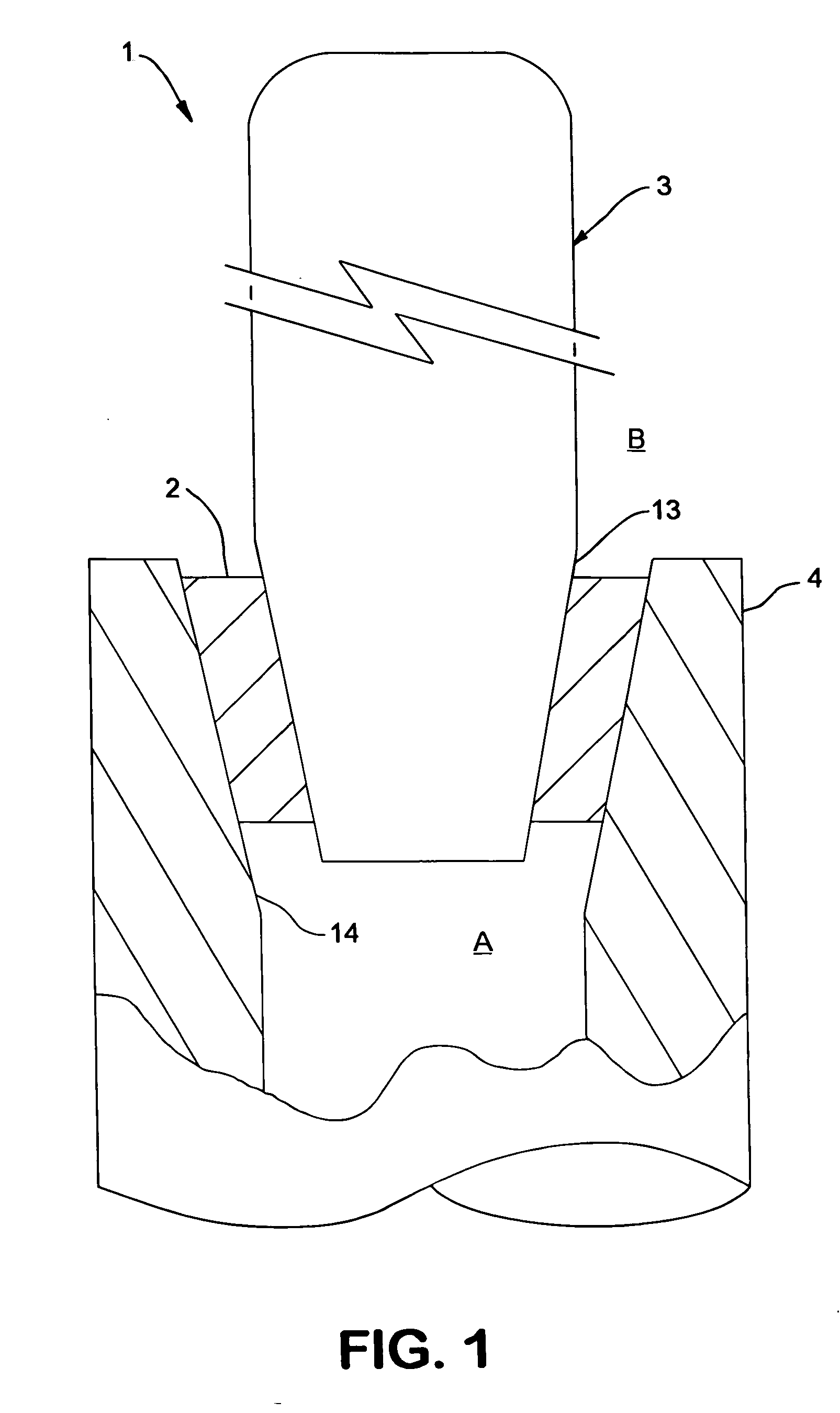
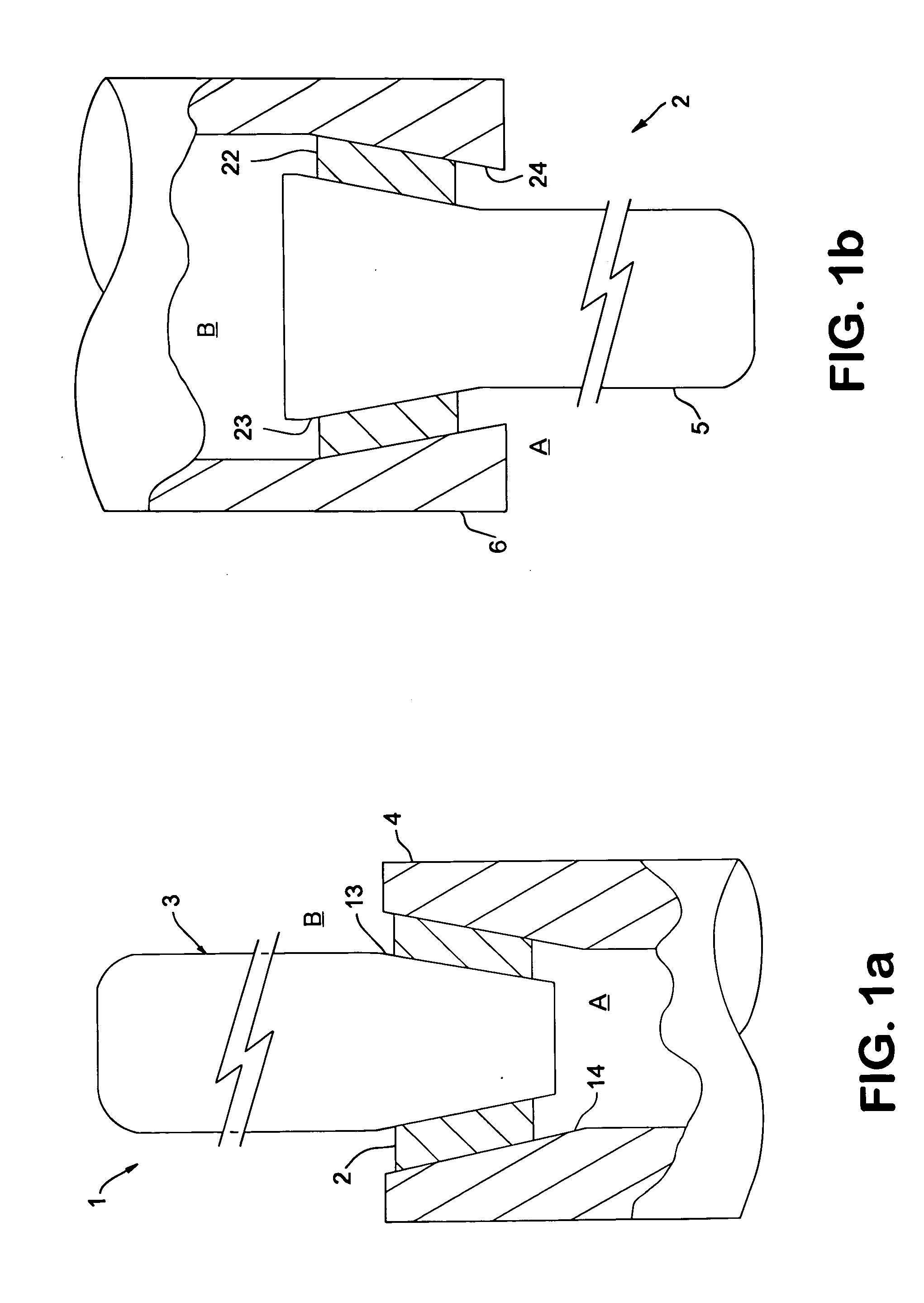
[0091] This example demonstrates preparation of a joint resistant to fluid leakage according to one aspect of the invention. A gas-tight ceramic comprising an oxygen transport material was fabricated in the form of a tube closed at one end (COE) and having a nominal outer diameter (OD) of 3 / 8 inch using an iso-static press with a pre-formed bag and mandrel. The ceramic tube had a tapered outer surface near its open end with a 3 degree angle of taper as measured from the axis of the tube. Except where otherwise noted, the tapered surface was polished with 350 grit grinding media in a hardened metal head resembling a pencil sharpener. This polishing is only optional, as an example below will illustrate. A girdle of cast gold was disposed between the tapered ceramic surface and a high strength metallic material (alloy) comprising HAYNES 230.

example 2

[0092] In this example, the joint described in Example 1 was tested over many thermal cycles at pressure differential across the membrane of from about 60 to about 180 pounds per square inch differential (psid).

[0093] The entire apparatus was placed in a pipe of HAYNES 230 alloy (nominal 1½″ diameter). A high pressure nitrogen purge rate was 4 L / min. on the fuel side of the membrane, and a low pressure nitrogen purge rate was 2 L / min. on the air side of the membrane. The pipe containing the apparatus was inserted into a furnace that has heated at a rate of 1.2° C. per minute to 975° C., and held at 975° C. during operation.

[0094] As shown in FIG. 2, the temperature was increased to 975° C. and then cooled between 20° C. and 200° C. The pressure in the reactor was maintained above 60 psid and as high as 180 psid. The pressure spikes were from increasing the pressure to operate under syngas process conditions. Therefore, each time the process gases of methane and steam were brought ...

example 3

[0095] In this example, the joint and COE oxygen transport membrane described in Example 1 were demonstrated to under go syngas process cycles converting methane and steam at a ratio of 1 to 2 into syngas at near equilibrium conditions at about 975° C. to about 1000° C. The air side of the membrane was at near ambient pressure whereas the syngas side of the membrane was as high as 180 psid. As shown in FIG. 3, an oxygen Flux of 8 sccm / cm2 was achieved. The leak tight seal allows the oxygen transport membrane to act as an oxygen compressor hence the membrane is 100 percent selective to oxygen transport. Any leakage through the joint could easily have been detected by a temperature rise as recorded with thermal couples placed on the air side of the membrane. The high-pressure methane fuel would burn with ambient pressure air. These temperatures can be very high which melt the seal, membrane, and metal holder. Typically carbon dioxide and moisture sensors were placed in the spent air t...


PUM

PropertyMeasurementUnit
temperaturesaaaaaaaaaa
pressuresaaaaaaaaaa
temperaturesaaaaaaaaaa

Abstract

Composite joints for gas-tight members that exhibit different coefficients of thermal expansion are disclosed. Broadly, apparatus of the invention provides composite joints which include a girdle of a resilient material disposed between mating surfaces of a high strength metallic member and a nonmetallic member in an arrangement wherein a difference in fluid pressures across the joint provides compressive force upon the girdle through tapered mating surfaces thereby improving resistance to fluid leakage. Composite joints of the invention are particularly useful for joining a high strength weldable metallic conduit and a gas-tight ceramic member having a tubular structure, closed at one end, with a tapered mating surface at a distal end thereof contiguous with a portion of the girdle. Processes beneficially using joints in accordance with the invention include converting methane gas into value-added-products, for example, production of synthesis gas comprising carbon monoxide and molecular hydrogen. Advantageously, the synthesis gas is free of deleterious and / or inert gaseous diluents such as nitrogen.

Description

FIELD OF THE INVENTION [0001] The present invention relates to composite joints for gas-tight members that exhibit different coefficients of thermal expansion. More particularly, this invention relates to composite joints resistant to fluid leakage which include a girdle of a resilient material disposed between mating surfaces of a high strength metallic member and a nonmetallic member in an arrangement wherein a difference in fluid pressures across the joint provides compressive force upon the girdle. Composite joints of the invention are particularly useful for joining a high strength metallic conduit and a gas-tight ceramic member wherein the ceramic member has a tubular structure, closed at one end, with a tapered mating surface at a distal end thereof and the mating surface is contiguous with a portion of the girdle. [0002] Processes beneficially using joints in accordance with the invention include converting methane gas into value-added-products, for example, production of sy...

Claims


Application Information

Patent Timeline
Patent Type & Authority Applications(United States)
IPC IPC(8): F16L47/00
CPCF16L25/0072
Inventor KLEEFISCH, MARK S.MASIN, JOSEPH G.COLLINS, JOHN P.XU, SHERMANUDOVICH, CARL A.
Owner BP CORP NORTH AMERICA INC
Why Eureka
Try Eureka