Planographic printing plate precursor

Inactive Publication Date: 2005-09-15
FUJIFILM CORP +1
View PDF13 Cites 4 Cited by
  • Summary
  • Abstract
  • Description
  • Claims
  • Application Information

AI Technical Summary

Benefits of technology

[0042] From this standpoint, one example of the resin which can be used together with the specified phenol resin is a water-insoluble alkali-soluble resin. Especially, preferable examples include polyamide resin, epoxy resin, polyacetal resin, acrylic resin, methacrylic resin, polystyrene resin and novolak-type phenol resin.
[0043] The mixing amount thereof is preferably up to 50% by mass relative to the specified phenol resin.
[0044] The upper layer of the invention is characterized by containing a water-insoluble alkali-soluble resin (hereinafter, referred sometimes to as an “alkali-soluble resin”) and an infrared absorber, and in that the solubility of the upper layer in an aqueous alkali solution is increased by exposure. The components of the upper layer of the invention will be described below.
[0045] The alkali-soluble resin that may be used in the upper layer of the invention is not particularly limited insofar as it has such characteristics as being soluble in an alkali deve

Problems solved by technology

On the other hand, in its exposed portions (non-image portions), interaction of the infra red dye with the binder resin is weakened by the heat generated.
Therefore, a problem arises in that an effect of development inhibiting function loss of the recording layer is not sufficiently obtained in the non-image area, and consequently, the difference between the image area and the non-image area decreases.
In particular, the reproducibility of highly fine images, such as halftone dots and thin lines, is insufficient.
If a recording layer comprising a material that allows the non-image area to be readily developed is used for this purpose, the planographic printing plate is susceptible to damage by the action of an ink cleaner and a plate cleaner used when printing, or of a developer or the like.
In other words, such a planographic printing plate is poor in chemical resistance and printing durability.
However, there remain some problems; for example, (1) the adhesion between the support and the recording layer is insuffici

Method used


Image

  • Planographic printing plate precursor
  • Planographic printing plate precursor
  • Planographic printing plate precursor

Examples


synthesis example 1

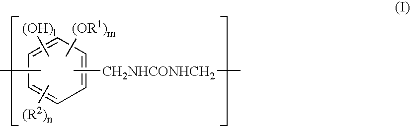
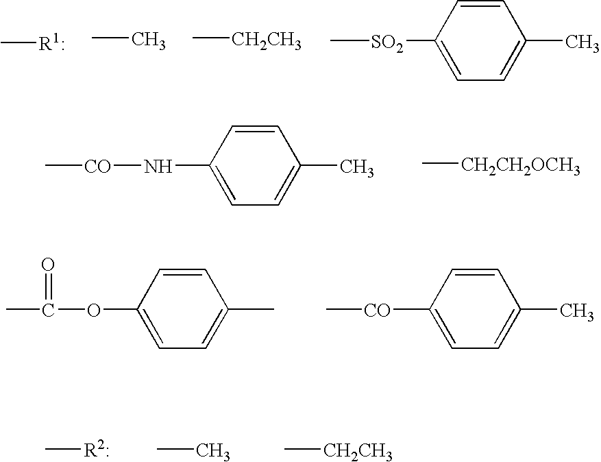
[0202] Into a 200-ml flask fitted with a stirrer and a heating device, 30 g of methanol and 5 g of N,N-dimethylacetamide were charged. Subsequently, 13.87 g (0.126 mole) of catechol and 13.76 g (0.115 mole) of N,N′-dimethylol urea were added. While the mixture was stirred at room temperature, 6 g of concentrated hydrochloric acid (12 N) was added and then heating was started. When the temperature reached 55° C., the temperature was maintained and the mixture was allowed to react at 55-60° C. for 5 hours. When the reaction solution was poured into 400 ml of water while stirring, a pale yellow solid formed. The solid was separated by filtration and dried. Thus, 20 g of specified phenol resin (1) was obtained. The yield was 72%.

synthesis examples 2-4

[0203] Resins were obtained in the same manner as in Synthesis Example 1 except that one of the starting materials, 13.87 g (0.126 mole) of catechol, was changed to 15.64 g (0.126 mole) of 3-methylcatechol, 15.64 g (0.126 mole) of 4-methylcatechol, and 17.64 g (0.126 mole) of 3-methoxycatechol, respectively. 25 g of specified phenol resin (2) (yield 85%), 23 g of specified phenol resin (3) (yield 78%) and 22 g of specified phenol resin (4) (yield 75%) were respectively obtained.

synthesis example 5

[0204] Into a 500-ml flask fitted with a stirrer and a heating device, 150 g of methanol and 15 g of water were charged. Subsequently, 63.05 g (0.50 mole) of pyrogallol and 50.0 g (0.45 mole) of N,N′-dimethylol urea were added and dissolved while stirring. 7.0 g of concentrated hydrochloric acid (12 N) was added to the mixture and then heating was started. When the temperature reached 55° C., the temperature was maintained and the mixture was allowed to react at 55-60° C. for 7 hours. After completion of the reaction the reaction solution was poured into 1000 ml of water while stirring. The solid formed was separated by filtration and dried. Thus, 89 g of specified phenol resin (5) was obtained. The yield was 79%.


PUM


Abstract

A planographic printing plate precursor comprises: a support; and a recording layer disposed on the support, the recording layer comprising a lower layer and an upper layer disposed on the lower layer, wherein the lower layer contains a resin having in a main chain structure a phenol skeleton and a urea bond, the upper layer contains a water-insoluble alkali-soluble resin and an infrared absorber, and the solubility of the upper layer in an aqueous alkali solution is increased by exposure. The planographic printing plate precursor can be produced directly through scanning exposure based on digital signals. It is superior in reproducibility of highly fine images and also superior in printing durability and chemical resistance of small-area image areas such as halftone dots and thin lines.

Description

CROSS-REFERENCE TO RELATED APPLICATION [0001] This application claims priority under 35 USC 119 from Japanese Patent Application No. 2004-69478, the disclosure of which is incorporated by reference herein. BACKGROUND OF THE INVENTION [0002] 1. Field of the Invention [0003] The present invention relates to a planographic printing plate precursor that can be used as an offset printing master. More particularly, it relates to a so-called positive planographic printing plate precursor for direct plate-making capable of forming a printing plate directly from digital signals from a computer or the like. [0004] 2. Description of the Related Art [0005] The development of lasers for planographic printing in recent years has been remarkable. In particular, high-power, small-sized solid lasers and semiconductor lasers that emit near-infrared and infrared rays have become easily obtainable. In the field of planographic printing, these lasers are very useful as exposure light sources when formin...

Claims


Application Information

Patent Timeline
IPC IPC(8): G03F7/11B41C1/00B41C1/10G03C1/52G03F7/00G03F7/004
CPCB41C1/1016B41C2201/04B41C2201/14B41C2210/02B41C2210/262B41C2210/14B41C2210/22B41C2210/24B41C2210/06
Inventor NAGASHIMA, AKIRA
Owner FUJIFILM CORP
Why Eureka
Try Eureka