Digital ultrasound beam former with flexible channel and frequency range reconfiguration

a beam former and flexible technology, applied in the field of ultrasound imaging methods and instruments, can solve the problems of reducing the dynamic range of the signal and hence the required number of bits, increasing the center frequency and bandwidth, and increasing the cost of the beam former per channel, so as to reduce the signal bandwidth, reduce the cost of the beam former, and increase the sampling rate

Inactive Publication Date: 2005-09-15
ANGELSEN BJORN A J +1
View PDF6 Cites 46 Cited by
  • Summary
  • Abstract
  • Description
  • Claims
  • Application Information

AI Technical Summary

Benefits of technology

[0016] The digital dynamic range can be increased with lower signal bandwidths by using increased sampling rates related to the bandwidth (over sampling), followed by digital low pass filtering of the signals that increases the number of bits and reduces the sampling rate.

Problems solved by technology

The cost of the beam former per channel is dominated by the cost of the ADCs, which increases with number of bits and highest sampling frequency of the ADC.
Non-cardiac imaging requires less dynamic range and number of bits in the ADCs, and an increase in the center frequency and the bandwidth further reduces the dynamic range in the signal and hence the required number of bits.
Manufacturing technology gives a limitation on the lowest pitch of the array elements, where λ / 2 pitches are achievable for frequencies up to 10 MHz with current transducer array technology.

Method used


Image

  • Digital ultrasound beam former with flexible channel and frequency range reconfiguration
  • Digital ultrasound beam former with flexible channel and frequency range reconfiguration
  • Digital ultrasound beam former with flexible channel and frequency range reconfiguration

Examples


Embodiment Construction

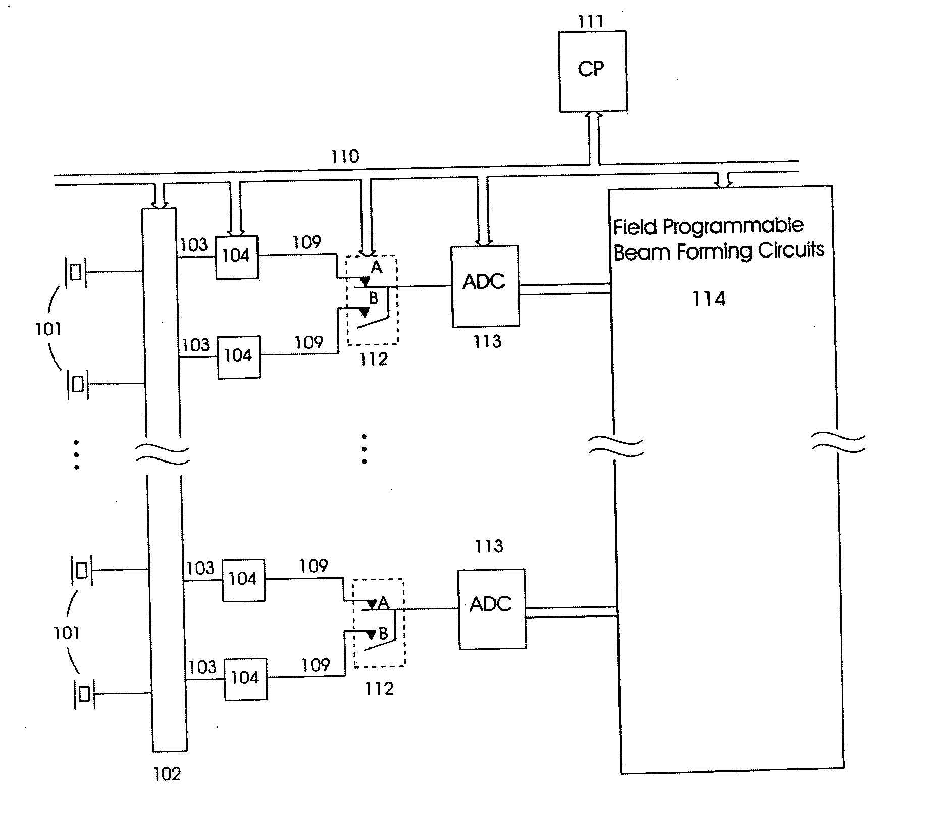
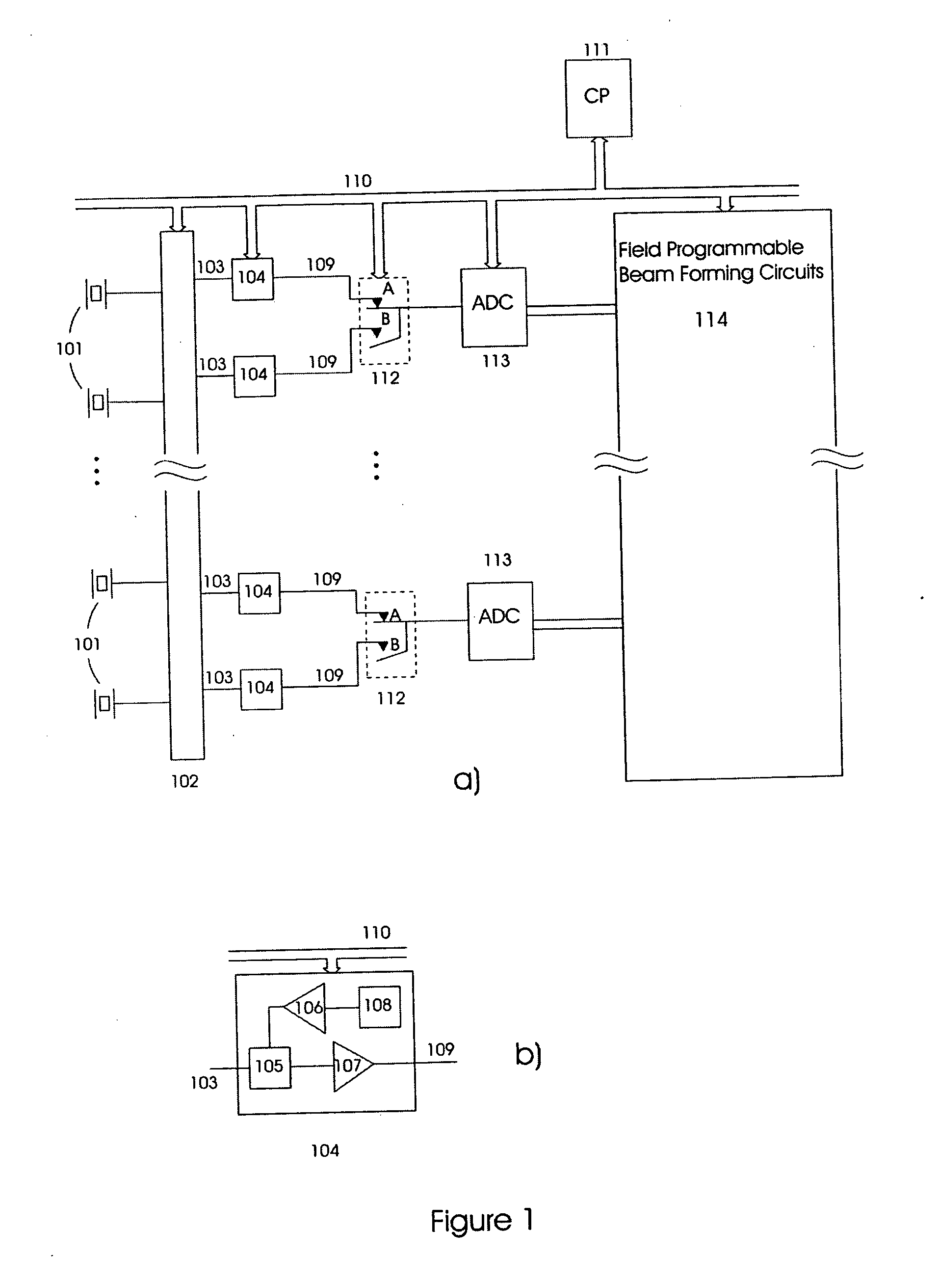
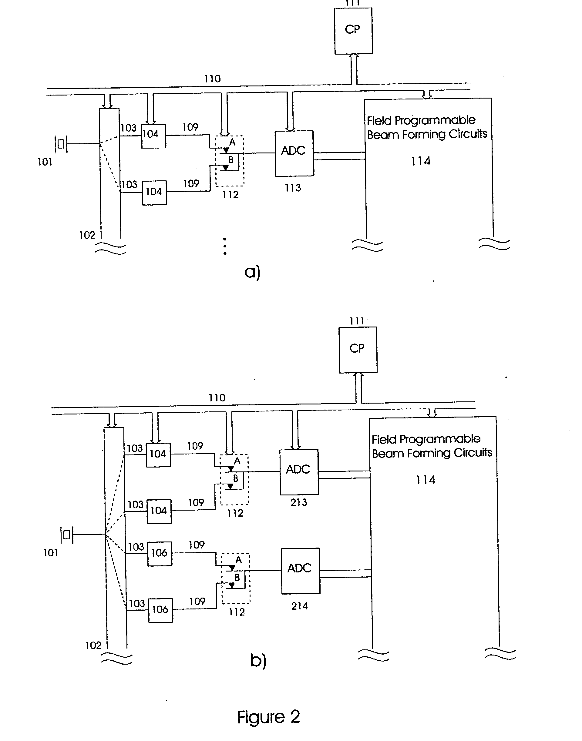
[0022]FIG. 1 illustrates one embodiment in the general spirit of the invention, where 101 indicates elements in an ultrasound transducer array, where each element is connected to an array coupling means 102, that provides selectable connection of the array elements to the inputs 103 of sets 104 of T / R (transmit / receive) circuits.

[0023] Essential elements of the T / R circuits are shown in FIG. 1b, where the input 103 connects to a transmit / receive switch 105, that connects the transducer array to transmit amplifiers 106 during the pulse transmit period, and to receiver amplifiers 107 during the receive period. The transmit amplifiers are driven from signal generators 108 that are set up via the bus 110 by the control processor 111. The transmit pulse can be triggered by a signal on the bus or through other means. The generator for example provides a delayed pulse transmit, where the delay is set for adequate focusing and direction steering of the transmit beam. The delay can also inc...


PUM


Abstract

A digital ultrasound beam former for ultrasound imaging, that can be configured by a control processor to process the signals from ultrasound transducer arrays with variable number of elements at variable sampling frequencies, where the lowest sampling frequency allows for the highest number of array elements. The maximal number of array elements is reduced in the inverse proportion to the sampling frequency. Parallel coupling of transmit/receive circuits for each element allow adaption of the receive Noise Figure and transmit drive capabilities to variations in the electrical impedance of the array elements.

Description

RELATED APPLICATIONS [0001] This application claims priority from U.S. Provisional Patent Application Ser. No. 60 / 543,241 which was filed on Feb. 9, 2004.BACKGROUND OF THE INVENTION [0002] 1. Field of the Invention [0003] The present invention is directed to methods and instrumentation of ultrasound imaging in a wide frequency range where the digital beamformer is reconfigurable in terms of number of channels versus frequency range. [0004] 2. Description of the Related Art [0005] Digital ultrasound beam formers for medical ultrasound imaging have the last decade become feasible due to improved functionality of analog to digital converters (ADCs) and digital integrated circuit technology. However, the requirements on the beam former in terms of number of channels, frequency bandwidth, signal dynamic range, etc., highly depend on the application and the resolution versus depth penetration required. [0006] The cost of the beam former per channel is dominated by the cost of the ADCs, wh...

Claims


Application Information

Patent Timeline
Patent Type & Authority Applications(United States)
IPC IPC(8): A61B8/02A61B8/06A61B8/12G01S7/52G10K11/34
CPCG10K11/341G01S7/52025
Inventor ANGELSEN, BJORN A.J.JOHANSEN, TONNI F.
Owner ANGELSEN BJORN A J
Why Eureka
Try Eureka