Valve prosthesis for implantation in body channels

a valve prosthesis and valve technology, applied in the direction of prosthesis, catheter, blood vessel, etc., can solve the problems of mainly difficulty in breathing, patients can have syncope, and difficulty in breathing, and the evolution of such a disease is disastrous

Inactive Publication Date: 2005-09-15
EDWARDS LIFESCI PVT
View PDF91 Cites 443 Cited by
  • Summary
  • Abstract
  • Description
  • Claims
  • Application Information

AI Technical Summary

Benefits of technology

[0020] Another aim of the present invention is to provide an efficient prosthesis valve which can be implanted by a catheterization technique, in particular in a stenosed aortic orifice, taking advantage of the strong structure made of the distorted stenosed valve and of the large opening area produced by preliminary balloon inflation, performed as an initial step of the procedure.
[0048] 2) needing a very strong structure able to resist the recoil force of the stenosed valve and capable of resisting, without any damage, a strong pressure inflation of the expanding balloon.

Problems solved by technology

In such aortic diseases, the patients can have syncope, chest pain, and mainly difficulty in breathing.
The evolution of such a disease is disastrous when symptoms of cardiac failure appear, since 50% of the patients die in the year following the first symptoms of the disease.
Unfortunately, a good result is obtained only in about half of the cases and there is a high restenosis rate, i.e., about 80% after one year.
Until now, the implantation of a valve prosthesis for the treatment of aortic stenosis is considered unrealistic to perform since it is deemed difficult to superpose another valve such an implantable valve on the distorted stenosed native valve without excising the latter.
However, this technique has been abandoned by most physicians because of the very high restenosis rate which occurs in about 80% of the patients within 10 to 12 months.
Indeed, immediately after deflation of the balloon, a strong recoil phenomenon often produces a loss of half or even two thirds of the opening area obtained by the inflated balloon.
This is due to the considerable recoil of the fibrous tissue of the diseased valve.
The drawback in this procedure has also been clearly shown on fresh post mortem specimens.
However, this type of design is inherently fragile, and such structures are not strong enough to be used in the case of aortic stenosis because of the strong recoil that will distort this weak structure and because they would not be able to resist the balloon inflation performed to position the implantable valve.
Furthermore, this valvular structure is attached to a metallic frame of thin wires that will not be able to be tightly secured against the valve annulus.
Such a light stent structure is too weak to allow the implantable valve to be forcefully embedded into the aortic annulus.
Moreover, there is a high risk of massive regurgitation (during the diastolic phase) through the spaces between the frame wires which is another prohibitive risk that would make this implantable valve impossible to use in clinical practice.

Method used


Image

  • Valve prosthesis for implantation in body channels
  • Valve prosthesis for implantation in body channels
  • Valve prosthesis for implantation in body channels

Examples


Embodiment Construction

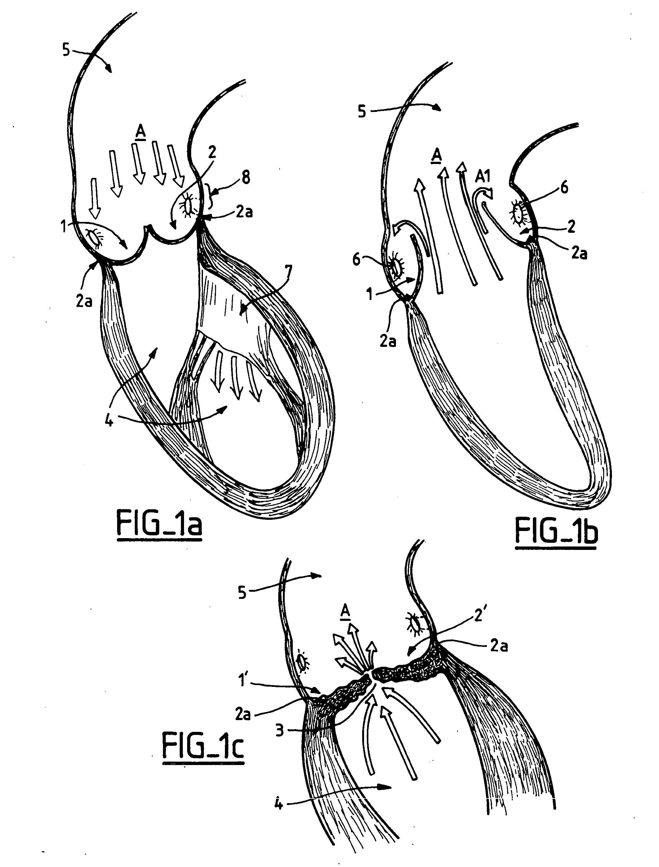
[0068] In the diastole and systole illustrations of section views of FIGS. 1a and 1b, the arrows A indicates the general direction of the blood flow. The semi-lunar leaflets 1 and 2 of a native aortic valve (with only two out of three shown here) are thin, supple and move easily from the completely open position (systole) to the closed position (diastole). The leaflets originate from an aortic annulus 2a.

[0069] The leaflets 1′ and 2′ of a stenosed valve as illustrated in FIG. 1c, are thickened, distorted, calcified and more or less fused, leaving only a small hole or a narrow slit 3, which makes the ejection of blood from the left ventricle cavity 4 into the aorta 5 difficult and limited. FIGS. 1a to 1c show also the coronary artery ostium 6a and 6b and FIG. 1 a shows, in particular, the mitral valve 7 of the left ventricle cavity 4.

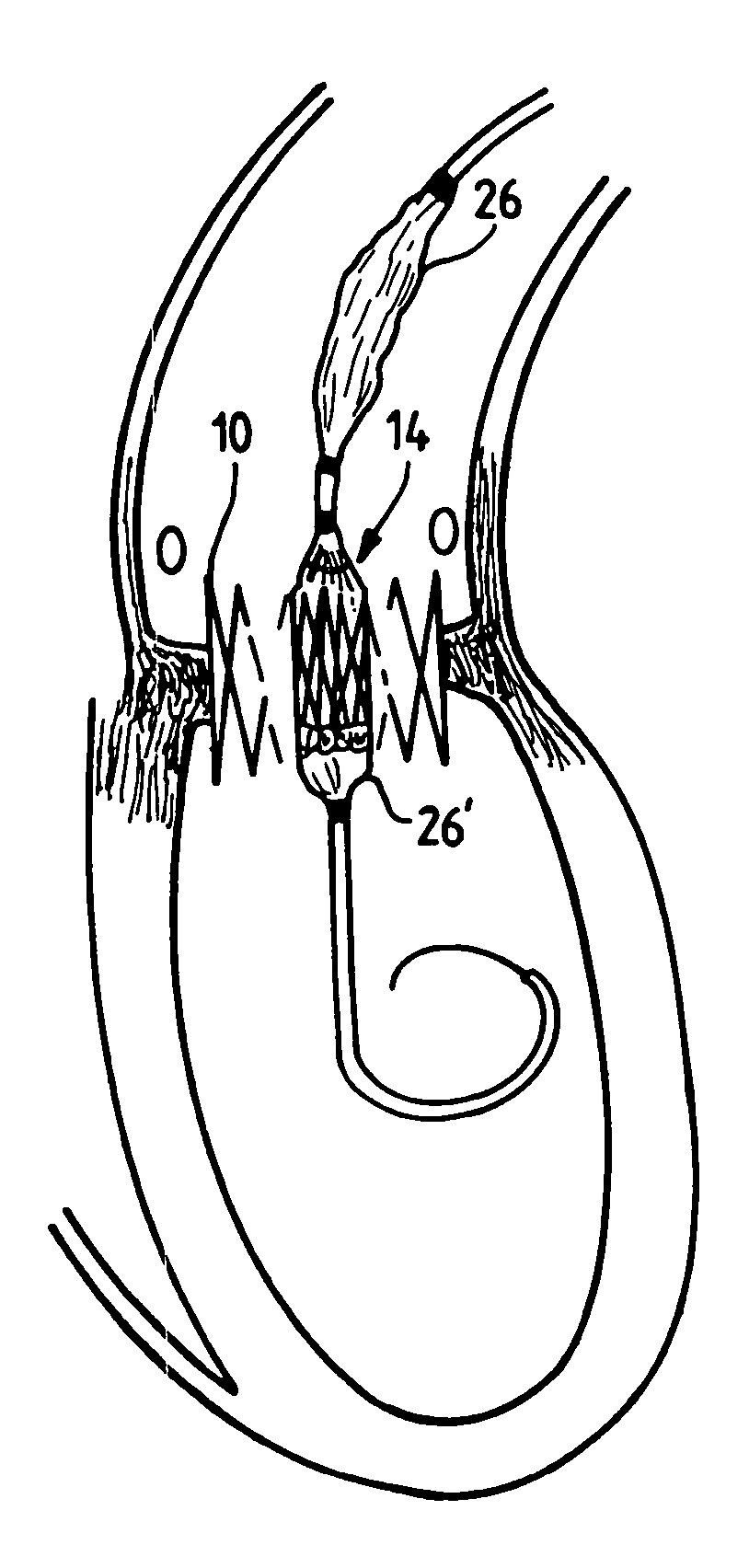
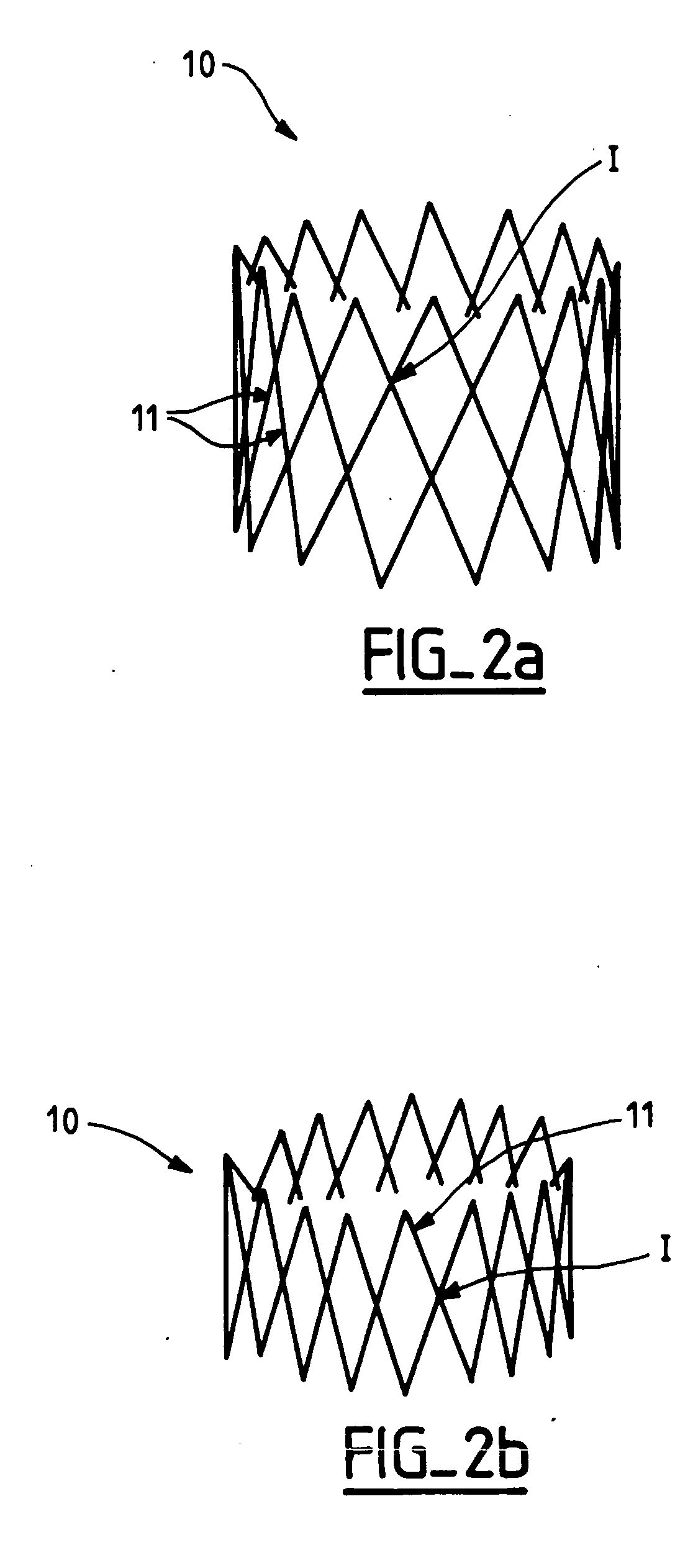
[0070] An implantable valve according to the invention essentially comprises a supple valvular structure supported by a strong frame. The positioning ...


PUM


Abstract

A valve prosthesis which is especially useful in the case of aortic stenosis and capable of resisting the powerful recoil force and to stand the forceful balloon inflation performed to deploy the valve and to embed it in the aortic annulus, comprises a collapsible valvular structure and an expandable frame on which said valvular structure is mounted. The valvular structure is composed of physiologically compatible valvular tissue that is sufficiently supple and resistant to allow the valvular structure to be deformed from a closed state to an opened state. The valvular tissue forms a continuous surface and is provided with strut members that create stiffened zones which induce the valvular structure to follow a patterned movement in its expansion to its opened state and in its turning back to its closed state.

Description

CROSS-REFERENCE TO RELATED APPLICATIONS [0001] This application is a continuation of co-pending U.S. patent application Ser. No. 10 / 139,741, filed May 2, 2002, which is a continuation of co-pending U.S. patent application Ser. No. 09 / 795,803, filed Feb. 28, 2001, now abandoned, which in turn is a continuation of U.S. patent application Ser. No. 09 / 345,824, filed Jun. 30, 1999, now abandoned, which is a National Phase filing of PCT patent application No. PCT / EP 97 / 07337, filed Dec. 31, 1997 and designating the United States, all of which are incorporated herein by reference.BACKGROUND OF THE INVENTION [0002] The present invention relates to a valve prosthesis for implantation in body channels, more particularly but not only to, cardiac valve prosthesis to be implanted by a transcutaneous catheterization technique. [0003] The valve prosthesis can be also applied to other body channels provided with native valves, such as veins or in organs (liver, intestine, urethra . . . ). [0004] Th...

Claims


Application Information

Patent Timeline
Patent Type & Authority Applications(United States)
IPC IPC(8): A61B19/00A61F2/06A61F2/24A61F2/84A61F2/90B60K37/06
CPCA61B19/54A61F2/2412A61F2/2415A61F2/2418A61F2/2433A61F2230/0054A61F2250/006Y10S623/90Y10S623/904A61F2220/0008A61F2/2475A61B90/39A61F2230/0069A61F2/2409
Inventor CRIBIER, ALAIN
Owner EDWARDS LIFESCI PVT
Why Eureka
Try Eureka