Vital signs probe

a technology of vital signs and probes, applied in the field of vital signs probes, can solve the problems of inefficiency of packaging various sensors in a single housing, inconvenient use, and inconvenient use, so as to enhance tissue perfusion, improve performance, and improve the effect of perfusion

Inactive Publication Date: 2005-09-22
FRADEN JACOB
View PDF7 Cites 286 Cited by
  • Summary
  • Abstract
  • Description
  • Claims
  • Application Information

AI Technical Summary

Benefits of technology

[0019] A combination of a patient core temperature sensor and the dual-wavelength optical sensors in an ear probe or a body surface probe improves performance and allows for accurate computation of various vital signs from the photo-plethysmographic signal, such as arterial blood oxygenation (pulse oximetry), blood pressure, and others. A core body temperature is measured by two sensors, where the first contact sensor positioned on a resilient ear plug and the second sensor is on the external portion of the probe. The ear plug changes it's geometry after being inserted into an ear cana

Problems solved by technology

Just a mere packaging of various sensors in a single housing typically is not efficient for the following reasons: various sensors may require different body sites, different sensors may interfere with each other functionality, a combined packaging may be more susceptible to motion and other artifacts and the size and cost may be prohibiting.
While an ear is an excellent location for the temperature monitoring and an infrared probe may be very accurate when used intermittently, it doesn't lend itself to a continuous monitoring due to its strong sensitivity to a correct placement, motion artifacts, and adverse effects of the ear canal temperature on the infrared sensing assembly.
Yet, presence of an infrared optical system in the ear canal results i

Method used


Image

  • Vital signs probe
  • Vital signs probe
  • Vital signs probe

Examples


first embodiment

[0041] First Embodiment

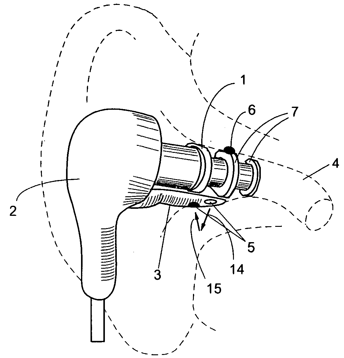
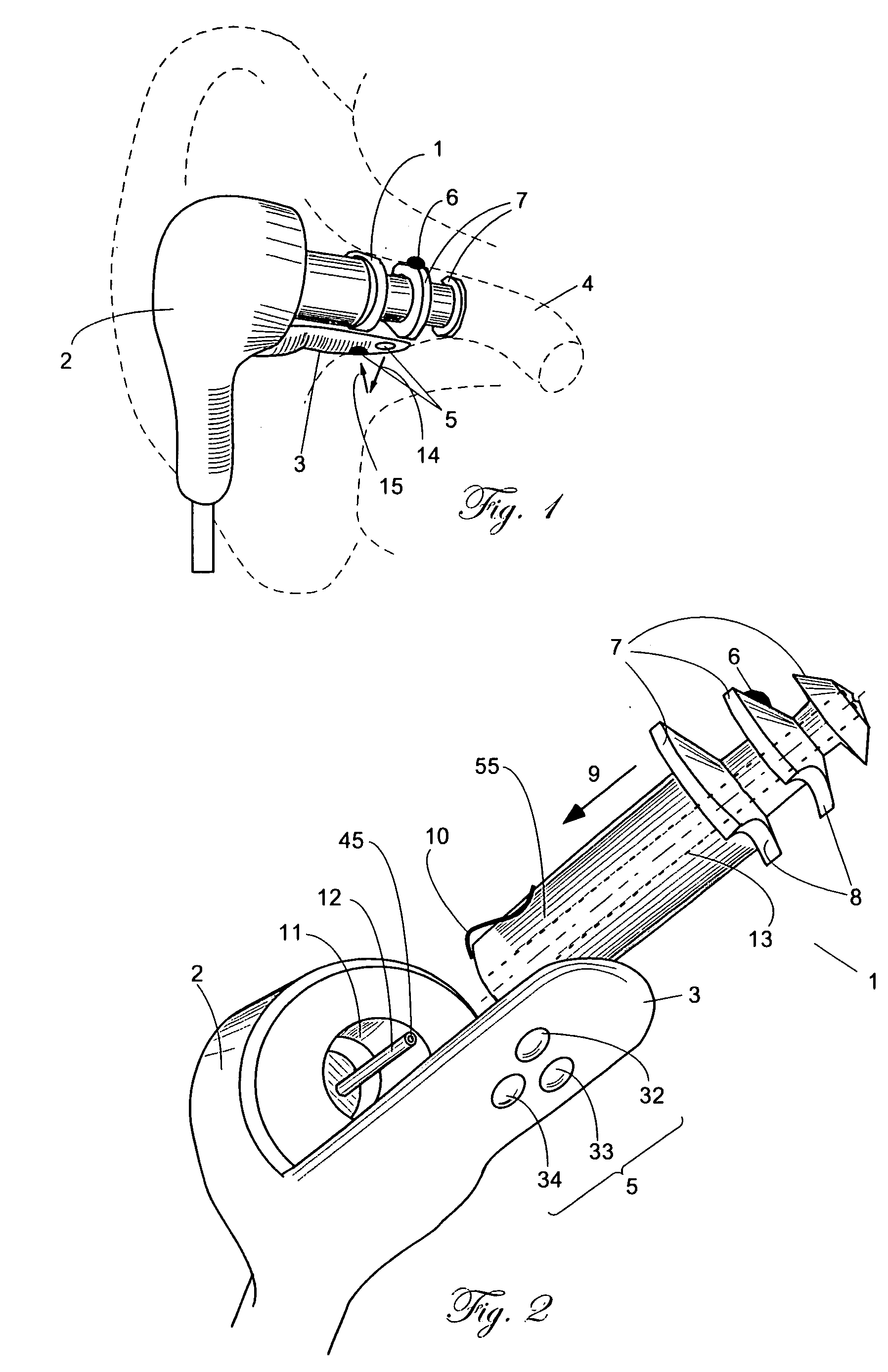
[0042]FIG. 1 shows plug 1 attached to ear probe 2. Probe 2 has a sensing extension 3 that carries blood oximetry windows 5. Plug 1 is fabricated of plaint, flexible and resilient material, such as silicone. A compressible foam also may be used.

[0043] Before the vital signs monitoring starts, plug 1 and extension 3 are inserted together into ear canal 4. This combination of extension 3 and a resilient ear plug 1 allows for a secure and stable positioning of the optical windows 5 against ear canal 4 walls. Extension 3 may be either rigid or somewhat flexible to accommodate variations of the ear canal shapes, while ear plug 1 is acting like a spring conforming its own contour to the ear canal shape and applying pressure on extension 3, pushing it against the ear canal wall. It should be appreciated that plug 1 has somewhat different shapes before, during and after insertion into the ear canal. Its original shape (before insertion) may have many configurations. H...

second embodiment

[0053] Second Embodiment

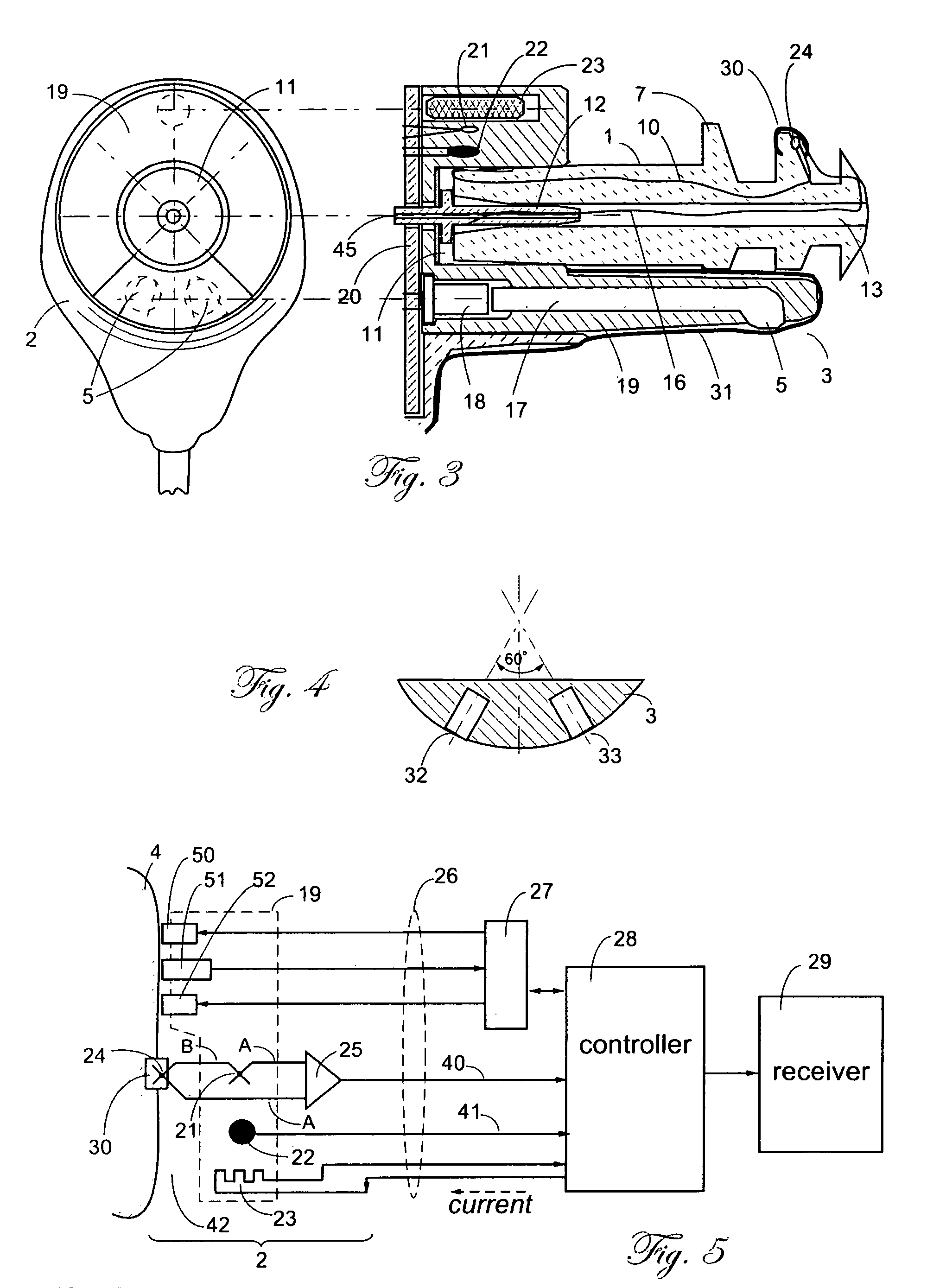
[0054] In this embodiment, photons of light that are modulated by the pulsatile blood to produce the photo-plethysmographic signals pass through a translucent ear plug. Thus, the essential component of this embodiment is a light transparent ear plug that also may be used as a carrier of a temperature sensor. Contrary to the first embodiment, when the optical components were incorporated into extension 3, the ability of an ear plug to transmit light allows to keep most of the optical components outside of the ear canal and thus simplifies design and use of the device.

[0055] Since the pulse oximetry data and indirect blood pressure monitoring can be accomplished from signals that are measured by the same optical probe, the same components that are used for the ear pulse oximetry are fully applicable for the indirect arterial blood pressure monitoring as well.

[0056] The light emitting devices (for example, light emitting diodes—LED) are positioned inside probe...

third embodiment

[0066] Third Embodiment

[0067] The above described sensing assemblies can be modified for use on an outside surface of a patient body, preferably above a bone, such as a scull or rib. FIG. 14 depicts a front plate that is to be placed on the patient skin. Like in the ear probe, it contains all essential components, such as heat equalizer 259 (analogous to equalizer 19), button 30, windows 250, 151 and 252, heater 69, cable 226. Thermal insulator 260 serves the same thermal function as probe 64 of FIG. 9. Insulator 260 may be made of polymer foam or it may be just a void inside the body of probe 275. The interior of the skin sensor is shown in FIG. 15 where first thermocouple junction 24 is positioned inside button 30 that makes intimate thermal contact with patient's skin 270. The button may be permanently attached to insulator 260, or alternatively, as shown in FIG. 15, it may be positioned on a disposable protective cup 265. That cup may be made of such material as polypropylene an...


PUM


Abstract

A combination of a patient core temperature sensor and the dual-wavelength optical sensors in an ear probe or a body surface probe improves performance and allows for accurate computation of various vital signs from the photo-plethysmographic signal, such as arterial blood oxygenation (pulse oximetry), blood pressure, and others. A core body temperature is measured by two sensors, where the first contact sensor positioned on a resilient ear plug and the second sensor is on the external portion of the probe. The ear plug changes it's geometry after being inserted into an ear canal and compress both the first temperature sensor and the optical assembly against ear canal walls. The second temperature sensor provides a reference signal to a heater that is warmed up close to the body core temperature. The heater is connected to a common heat equalizer for the temperature sensor and the pulse oximeter. Temperature of the heat equalizer enhances the tissue perfusion to improve the optical sensors response. A pilot light is conducted to the ear canal via a contact illuminator, while a light transparent ear plug conducts the reflected lights back to the light detector.

Description

FIELD OF INVENTION [0001] This invention relates to devices for monitoring physiological variables of a patient and in particular to a device for monitoring arterial pulse oximetry and temperature from an ear canal. This invention is based on the provisional patent application Ser. Nos. 60 / 449,113 and 60 / 453,192. DESCRIPTION OF PRIOR ART [0002] Monitoring of vital signs continuously, rather than intermittently is important at various locations of a hospital—in the operating, critical care, recovery rooms, pediatric departments, general floor. etc. If accuracy is not compromised, the preference is always given to non-invasive methods as opposed to invasive. Also, a preference is given to a device that can provide multiple types of vital signs instead of receiving such information from many individual sensing devices attached to the patient. Just a mere packaging of various sensors in a single housing typically is not efficient for the following reasons: various sensors may require di...

Claims


Application Information

Patent Timeline
IPC IPC(8): A61B5/00A61B5/0205A61B5/021
CPCA61B5/02055A61B5/021A61B2562/247A61B5/1491A61B5/6817A61B5/14552A61B5/01
Inventor FRADEN, JACOB
Owner FRADEN JACOB
Why Eureka
Try Eureka