
Endoscopic suturing assembly and associated methodology using a temperature biased suture needle

Inactive Publication Date: 2005-09-22
GRANIT MEDICAL INNOVATION
View PDF19 Cites 85 Cited by
  • Summary
  • Abstract
  • Description
  • Claims
  • Application Information

AI Technical Summary

Benefits of technology

[0025] An additional alternative embodiment of the present invention, wherein the temperature control system utilizes electricity for providing heat to the suture needle, includes an electrical source providing electrical power, such as an electrical generator. The electrical source is operatively connected to an electrical connector and current is passed through said electrical connector and through an appropriate low resistance connection that is coupled to one or both of the high resistance metal jaws of the needle-grasping device. This delivery of power (e.g., electrical current) to a jaw assembly causes the jaws, and subsequently the needle that is being grasped by said jaws to become heated, thereby transforming a needle into its austenitic state. When the suture needle requires withdrawal at the termination of the procedure, cold water may be injected through the designated channel in the needle-grasping device directed to flow over a suture needle, thus rendering it malleable for withdrawal.
[0026] Alternatively, the collar that comprises the distal end of the delivery tube may be heated to direct heat to the needle. In another embodiment of the present invention, a delivery tube includes insulated low resistance wires coupled to a connector. The wires may extend along and be imbedded in the shaft of delivery tube. An electrical source is operably connected to an electrical connector thereby passing electrical power through said electrical connector and down the low resistance wires. The wires are distally connected to a high resistance metal collar. As current is transmitted along this embodiment, the metal collar becomes hot, thus transmitting heat to the needle thereby causing

Problems solved by technology

Morbidity and mortality resulting from these operations is relatively high.
These complex and invasive surgical procedures require general anesthesia, surgical incisions, lengthy periods of time in the hospital, significant use of medication for management of postoperative pain and lengthy periods of convalescence.
Surgical procedures to treat morbidly obese patients have a high incidence of complications and thus limit the number of patients who can benefit from these procedures.
Oftentimes the patient has had prior surgery causing adhesions, which bind the intestines together.
The surgery is technically more difficult and takes two to three hours longer than the open operation.
Consequently longer anesthesia time is required, increasing patient morbidity.
In order to perform gastric bypass surgery laparoscopically, the abdomen requires distention with air, which impinges on the patient's lungs thereby decreasing breathing capacity.
Yet, such procedures are currently limited to examinations that include biopsy and polypectomy within the lumen of the gastrointestinal tract.
One of the significant reasons for this limitation is the lack of the ability, with current surgery assemblies and techniques, to perform suturing and / or stapling through the narrow working channel of the flexible endoscope.
The device described in the '433 patent presents the various drawbacks and problems.
Any embodiment with a stiff length longer than 1 cm will not be capable of being passed through the working channel when the endoscope is bent, and will prevent the flexible endoscope from bending when housed inside its working channel.
If a needle were to be formed from a material stiff enough to effectively and consistently enter and exit tissue, it would surely not be malleable enough pass through the working channel of a flexible endoscope.
A further problem that the device described in the '433 patent presents is its lack of anticipation of the difficulty presented in grasping the suture needle with the manipulation device.
The '433 patent does not address such an issue.
Lastly, the '433 patent does not address the attachment of the suturing thread to the needle.
In the case of a needle made of a spring biased metal, the metal is too soft to retain the thread by mere crimping.

Method used


Image

  • Endoscopic suturing assembly and associated methodology using a temperature biased suture needle
  • Endoscopic suturing assembly and associated methodology using a temperature biased suture needle
  • Endoscopic suturing assembly and associated methodology using a temperature biased suture needle

Examples


Embodiment Construction

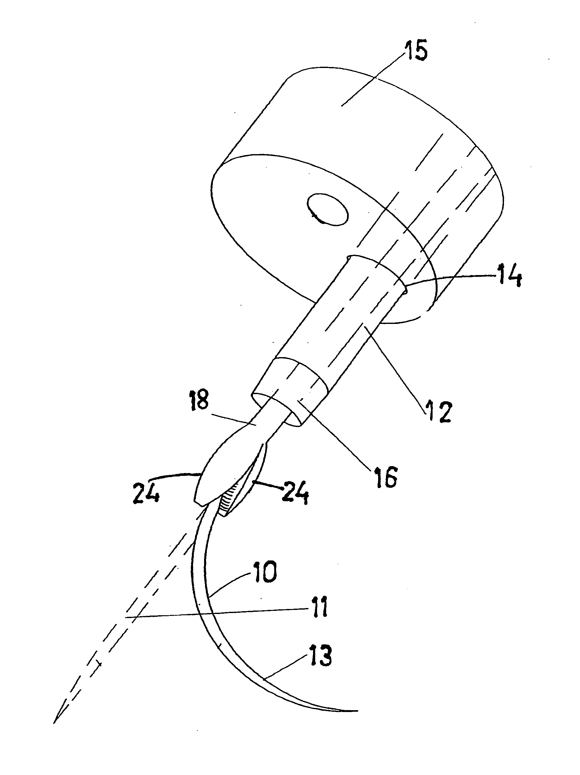
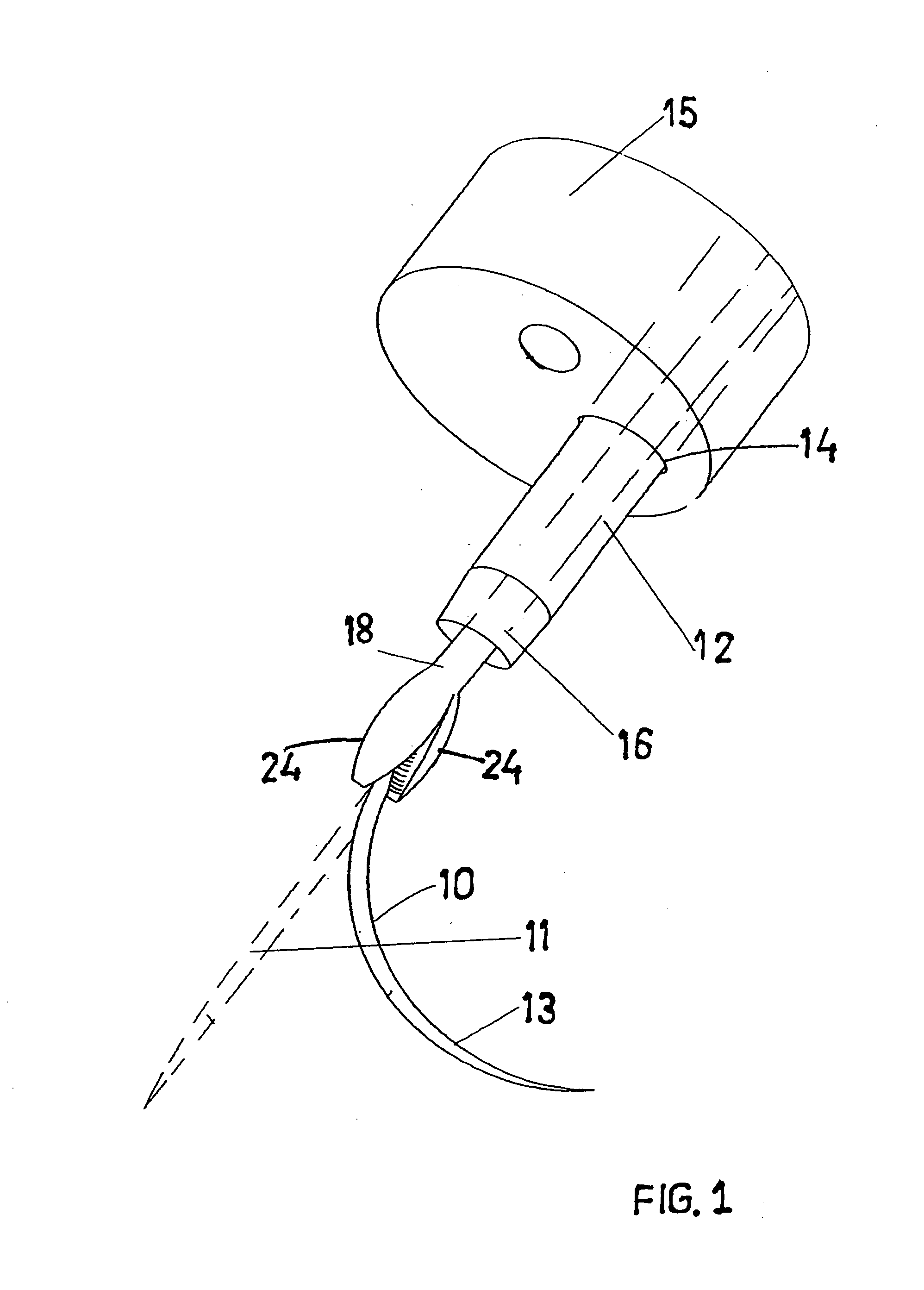
[0058] As illustrated in FIG. 1 an endoscopic surgery system or surgical assembly comprises a temperature biased suture needle 10, a needle-grasping device 18, and an elongated catheter or other delivery tube or tubular member 12, shown emerging from working channel 14 of an endoscope insertion member 15. Delivery tube or tubular member 12 is configured for insertion into the working channel 14 of endoscope insertion member 15. Needle grasping device 18 includes a flexible or rigid elongated shaft, a handle mechanism and a jaw assembly with jaws, and is movable within delivery tube 12 and is configured for grasping and manipulating suture needle 10. Suture needle 10 is shown in a straight malleable (martensitic) state 11 in dashed lines, and in a stiff, hardened, austenitic state 13. Suture needle 10 is in its malleable state 11 for passage through or manipulation inside working channel 14 of endoscope insertion member 15, and in its hardened arcuate shape for suturing tissue. Sutur...


PUM


Abstract

An endoscopic suture needle and related surgical endoscopic suturing devices are to be used in conjunction with an endoscope. The invention relates to suturing of internal body tissue as part of a surgical procedure which may be diagnostic, therapeutic or both. In accordance with the present invention, there is provided an endoscopic surgery system comprising a temperature biased suture needle, a needle grasping device, and an elongated catheter or other delivery tube, a endoscopic surgery system configured for use in conjunction with a flexible or rigid endoscope insertion member.

Description

[0001] This application claims the benefit of the priority of U.S. Provisional Application Ser. No. 60 / 549,275, filed on Mar. 2, 2004, entitled “Temperature Biased Suture Needle,” which application is incorporated herein by reference in its entirety.FIELD OF THE INVENTION [0002] The present invention relates to a surgical instrument assembly for use in suturing inside internal body cavities of a patient, and more specifically to an instrument assembly for use in conjunction with a flexible or rigid endoscope to suture tissue within the body. This invention has particular applicability for suturing in conjunction with an endoscope inside internal body cavities of a patient, for example, inside the abdomen by gaining access through an existing orifice. BACKGROUND OF THE INVENTION [0003] In a conventional abdominal surgical procedure, one or more incisions are created in the abdominal wall in order to enter the abdominal cavity. Surgical procedures to remove diseased tissue or organs a...

Claims


Application Information

Patent Timeline
IPC IPC(8): A61B17/04
CPCA61B17/062A61B2017/003A61B2017/2946A61B2017/06095A61B2017/00867
Inventor NAKAO, NAOMI L.
Owner GRANIT MEDICAL INNOVATION
Learn More