Precision feed end-effector composite fabric tape-laying apparatus and method

a technology of composite fabric and end-effector, which is applied in the direction of electrical programme control, mechanical control devices, programme control, etc., can solve the problems of increased weight of the final product, limited ability of the result to be an engineered product, and process tends to be very messy, and achieves simple configuration

Inactive Publication Date: 2005-09-22
COMPOSITE SYST
View PDF5 Cites 39 Cited by
  • Summary
  • Abstract
  • Description
  • Claims
  • Application Information

AI Technical Summary

Benefits of technology

[0016] The new invention abbreviated herein as ‘Precision Feed End-Effector’ or ‘PFE’, has been designed to overcome many of the issues defined above. It has been designed with both modularity

Problems solved by technology

To achieve the desired structural properties with the use of chopper gun technology the application of more product in a given area is the most common method; however, disadvantages of this method include increased weight of the final product and limited ability of the result to be an engineered product.
In either method of application this process tends to be very messy.
Tape laying machines have proven to be very accurate and reliable; however, because of the size and extreme costs associated with them, only a limited number of companies can provide product via this method.
Set-up can be very costly and time consuming due, in part, to the method by which the systems are programmed.
These systems are also limited, in that the plug, mold or mandrel must typically be placed ‘in position’ or that the tape is always placed with gravity assist.
A limiting factor with these machines is that the tape dispensing rolls have been limited in size, allowing for only 1.00″ to 12.00″ of material to be laid in a single pass, and subject to the amount of engineered overlap per seam.
Because of this limitation, additional weight is added to the product being constructed.
This, in turn adds to the time required for the lay-up itself and becomes an issue with respects to the out time allotted for a given resin system.
These machines do not lend themselves to the lay-up of dry fabrics such as those used in the construction of boat or ship hulls and deck components.
Autoclaves large enough to house such products are impractical and therefore limit the amount of pre-preg material that can be used, even by hand, unless mobile IR (infrared) modules are placed about the product for curing purposes.
These products are generally large and multi-faceted and/or concave, convex or combination surfaced and do not lend thems

Method used


Image

  • Precision feed end-effector composite fabric tape-laying apparatus and method
  • Precision feed end-effector composite fabric tape-laying apparatus and method
  • Precision feed end-effector composite fabric tape-laying apparatus and method

Examples


Embodiment Construction

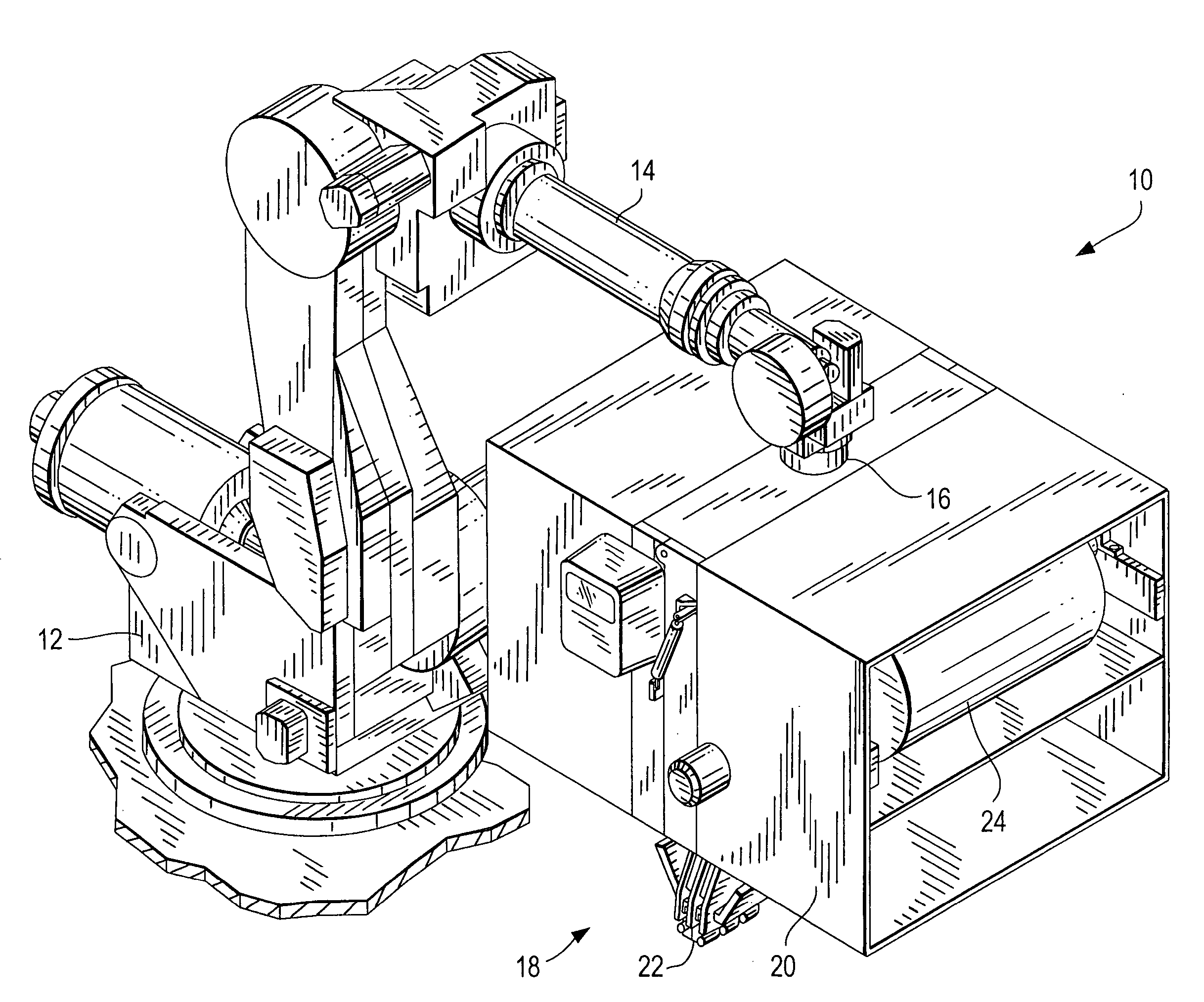
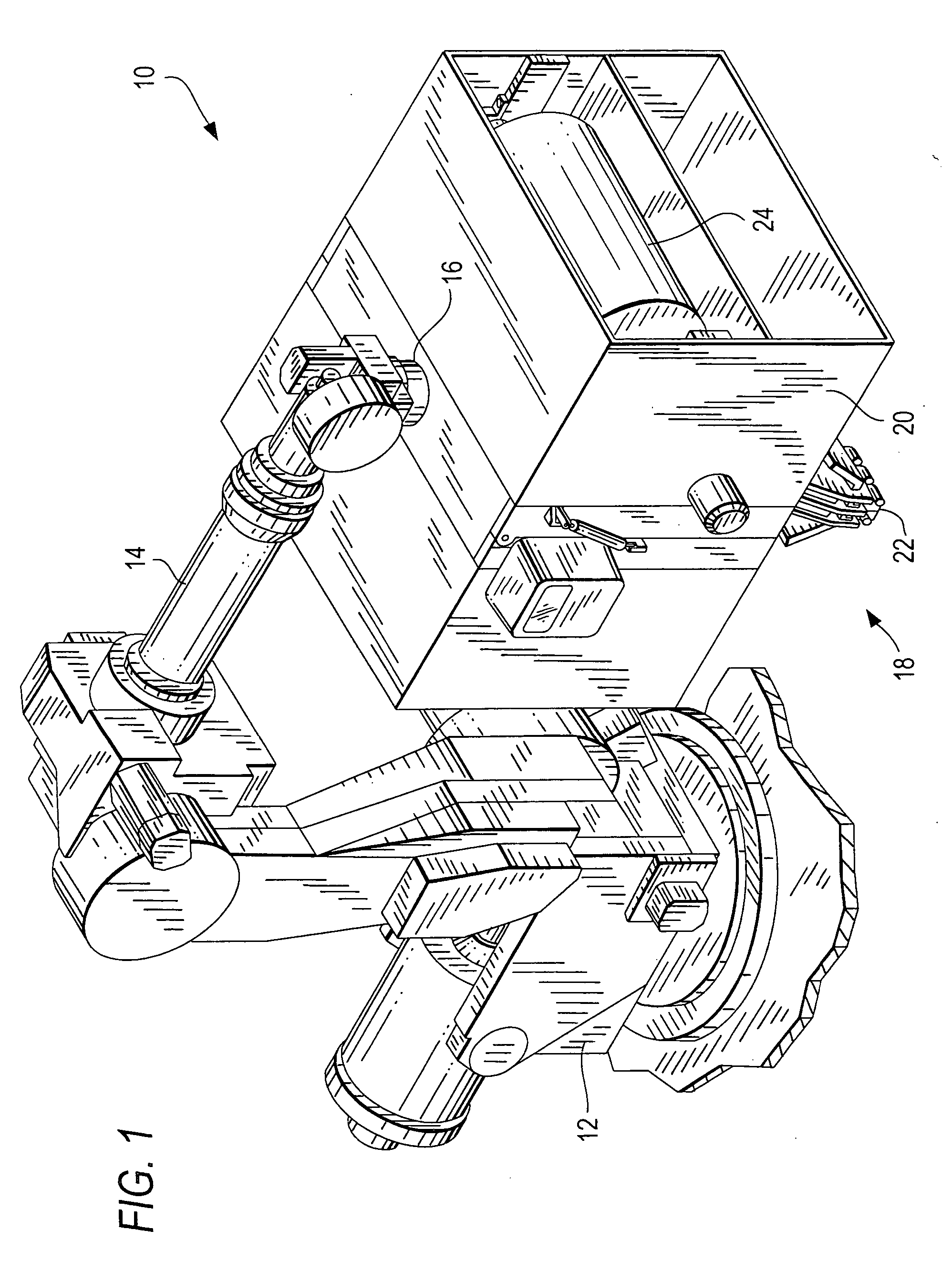
[0110] This invention is illustrated herein in the form of a first embodiment, shown primarily in FIGS. 1-18, where the PFE tape-laying head has four basic modules or module units, each having three rollers, and a second embodiment where the PFE has three basic modules. While both of these embodiments are shown with two side-by-side sets of basic modules where the tape is fed between them, the preferred embodiments of this invention comprise a variation of said first and second embodiments where one of said two side-by-side sets of basic modules is replaced by a guide plate as seen in FIG. 30. Thus, it should be understood that the descriptions of the first and second embodiments are intended to include this third embodiment variation. For convenience, some of the components in the second embodiment which are essentially the same as components in the first embodiment will be given the same reference number. As will be explained later, in both the first and second embodiments the rol...


PUM

PropertyMeasurementUnit
Lengthaaaaaaaaaa
Lengthaaaaaaaaaa
Angleaaaaaaaaaa

Abstract

A fabric and tape laying machine operable with: (a) a robot including programmable control means, (b) a supply roll containing a continuous strip of composite tape or fabric, and (c) a mold of predetermined surface shape relative to x, y and z coordinates, including: a. a chassis mountable to and movable by the robot, b. a contact roller module mounted on the chassis and spaced apart and downstream from the supply roll and adapted to receive tape from the supply roll, the contact roller module being moved along the programmed path by the chassis, c. a tape cutting unit carried by the chassis and situated between the supply roll and the contact roller module, and d. a suspension system for dynamically energizing the contact roller module to have its rollers apply a predetermined level of force downward on the tape during the lay-up process.

Description

[0001] This application claims priority of the Sep. 12, 2002 file date of applicant's provisional application, Ser. No. 60 / 410,066.FIELD OF THE INVENTION [0002] The present invention relates to apparatus and methods for composite fabric tape lay-up, including tape edge profiling and tape placement onto molds, plugs and mandrels and use of robots in combination with such apparatus. BACKGROUND OF THE INVENTION [0003] Composite fabrics, dry or pre-preg (pre-impregnated resin systems), including fiberglass, carbon fiber, graphite, ceramics, Kevlar, Aramid and other hybrids of uni-directional or bi-directional makeup have been used in the construction of a variety of products, including aircraft components, marine applications, automotive and various industrial and appliance applications to reduce weight while improving structural properties and aesthetic flexibility. These products lend themselves to products in size and shape typically not less than one square foot in surface area and ...

Claims


Application Information

Patent Timeline
IPC IPC(8): B29C70/38B63H9/06B65H35/00D04H3/04G06F19/00
CPCB29C70/32B29C70/388B29C70/545B63H9/0657Y10T156/1788B65H35/0013D04H3/04Y10T156/1365B63H2009/0678B63H9/067B63H9/0678
Inventor GROPPE, DAVID
Owner COMPOSITE SYST
Why Eureka
Try Eureka