Trilithic and/or twin shell dome type structures and method of making same

Inactive Publication Date: 2005-09-29
DEFEVER MICHAEL D +1
View PDF8 Cites 67 Cited by
  • Summary
  • Abstract
  • Description
  • Claims
  • Application Information

AI Technical Summary

Benefits of technology

[0024] Once the outer horizontal and vertical rebar framework has been attached by way of such lengthened hanger brackets the strategic application of Universal Snap In Standards (USIS Braces) serve to create the unique cavity or separation between the outer rebar reinforcement framework and an inner reinforcement framework. Once the inner-most horizontal rebar is snapped into the USIS brace receiver, the inner vertical rebar can be quickly attached thereby causing a multiple shell framework that is virtually self supporting. Shotcrete being then sprayed through the inner framework builds surface thickness over the outer framework and against the light weight and strengthened air-form which has become essentially a backdrop upon which shotcrete is applied, while specific attention is given to applying more shotcrete thickness at intersecting points where the USIS Braces connect to both vertical and horizontal rebar thus reinforcing all such attachment points to the outer

Problems solved by technology

South then discloses further in his second sentence of page 1 paragraph 3, that: “One drawback to these known dome structures is that they are restrictive in size.
As the inflatable air-form is made larger to produce a larger diameter dome, such as a diameter exceeding 300-400 feet, the higher air pressure required to inflate and raise the heavier form may cause the form to tear.
Such domes South states “have the further disadvantage that they are relatively complex and expensive to make, as compared to a dome structure as disclosed in U.S. Pat. No. 4,155,967 which cannot be constructed in excess of 300′ in diameter”.
S

Method used


Image

  • Trilithic and/or twin shell dome type structures and method of making same
  • Trilithic and/or twin shell dome type structures and method of making same
  • Trilithic and/or twin shell dome type structures and method of making same

Examples


Embodiment Construction

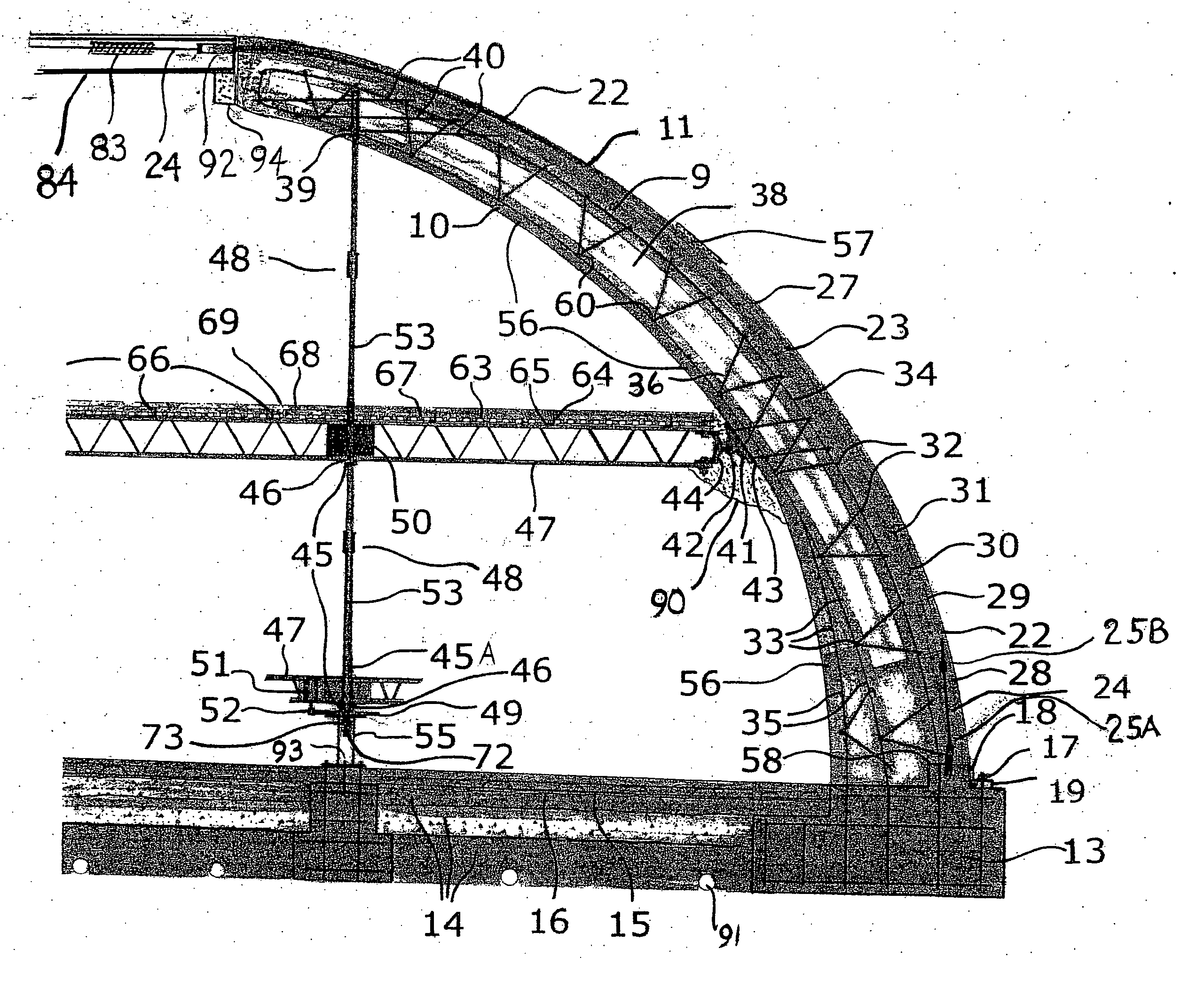
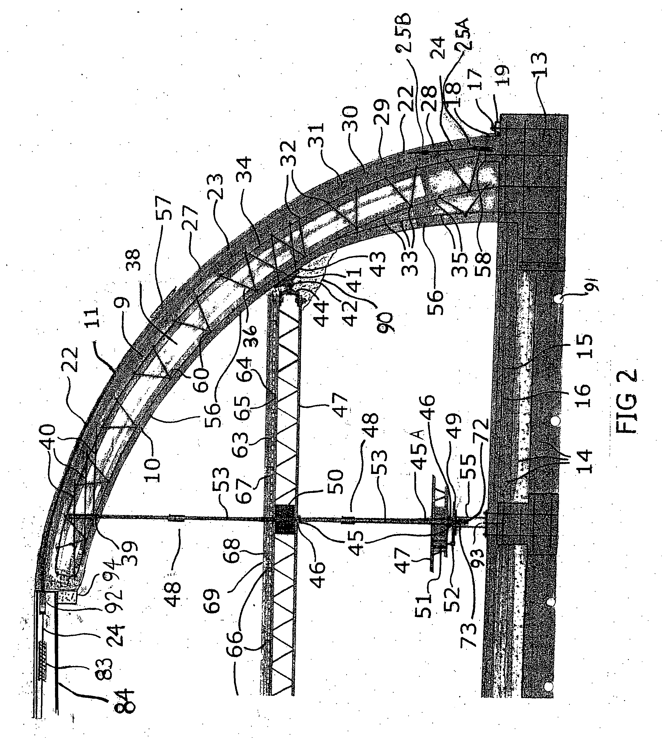
[0051] Referring now to the drawings, and in particular to FIGS. 1 and 2, a Twin Shell, Multiple Shell and / or Trilithic Dome Shell type structure constructed in accordance with one embodiment of the present invention is indicated generally in FIG. 1 and shall be herein after referred to in general as a Multiple Shell Type structure or (MST) structure.

[0052] The MST structure illustrated in FIG. 1, takes the form of a generally semi-spherical shaped dome building having a circular base defined by a footing or foundation 13 (FIGS. 1, 2, 4, 10, 11, 24) that is preferably formed from concrete to establish the desired base diameter and is sized to support the weight of the dome and to withstand various weather and environmental conditions to which such structures may be subjected.

[0053] Briefly the MST structure is constructed by first setting the foundation footing 13 (FIGS. 1, 2, 4, 10, 11, 24) after which a light weight and structurally reinforced air-impervious inflatable air-form ...


PUM


Abstract

Trilithic Shell, Twin Shell, Multiple Shell, Curvilinear Shell as well as Free-formed Structures described herein each employ an inflatable membrane having a peripheral edge secured to an outer foundation base. An ultra-light membrane (air-form) having a network of internal cross connecting restraints is additionally secured to the inner foundation base to permit a novel and unique curvilinear surface. Pressurization then creates the backdrop upon which various urethane layers are applied which when laced with rigidifying tubes become the defining backdrop beneath which numerous cross connecting braces which when snapped into position effectively lock an inner framework to an outer framework thereby producing a self supporting truss like structure both compatible with either current dome construction and/or conventional construction practices. Shotcrete being then sprayed from the interior over said urethane coated backdrop forms highs at framework intersections and natural lows in between followed by the insertion of inflated cell tubes which span the created network of horizontal and vertical cavities are next over sprayed with urethane foam necessary to form the next natural backdrop over which two or more shotcrete/steel reinforced separate yet cross connected planes may be achieved. Such multiple yet independent rigid layers now having thousands of inner-connecting cross braces through which interior voids become natural chase-ways effectively displace 50% or more of what might otherwise be solid concrete as would be the case with all prior art thin shell structures and/or conventional stem wall construction practices. Such Free Formed curve-linear structures effectively reduce material and labor costs by as much as 50%, eliminate snap-through or oil-can buckling tendencies, enhance overall structural capacity, eliminate all height to diameter restraints, permit larger structures, facilitate floor suspension and attachment, and allow mechanical, electrical and HVAC distribution through interior chase-ways which cannot be achieved with prior art concrete thin shell single thickness structures and/or conventional stem wall, construction practices to date.

Description

BACKGROUND OF THE INVENTION [0001] Present invention relates to conventional stem wall construction practices, roof shell construction practices, tunnel construction, and more specifically to concrete dome shell structures which are most commonly referred to as Thin Shell structures within in the industry. [0002] Such structures to date typically have been constructed utilizing numerous and / or various construction methods whereby a single shell thickness of concrete is achieved. Essentially, varying methods of layering dissimilar materials necessary to define the outer dimension of such structures and in particular dome structures have been used for decades by spraying concrete for example to either the inside and / or outside of a form. [0003] Structures for example being typically constructed by inflating an air-form, followed by applying an insulating urethane foam material to the interior of said air-form, followed by securing a reinforcing mesh and / or rebar to said urethane foam ...

Claims


Application Information

Patent Timeline
IPC IPC(8): E04B1/16E04B1/32E04B1/35
CPCE04B1/169E04B2001/3264E04B1/3511
Inventor DEFEVER, MICHAEL D.DEFEVER, RYAN MICHAEL
Owner DEFEVER MICHAEL D
Why Eureka
Try Eureka