Drive device for a secondary air injection system

a technology of secondary air injection and drive device, which is applied in mechanical equipment, machines/engines, electric control, etc., can solve the problems of system as a whole being damaged, system may not be able to adequately purify exhaust gas, and may not be able to meet the requirements of the application

Active Publication Date: 2005-09-29
DENSO CORP
View PDF7 Cites 19 Cited by
  • Summary
  • Abstract
  • Description
  • Claims
  • Application Information

AI Technical Summary

Benefits of technology

[0017] According to a tenth aspect, in case a signal input line connecting the high-order system to the signal processing means is grounded, the voltage at the input terminal of the signal processing means drops down to the ground potential level, and there is established a relationship “voltage at the input terminal<threshold voltage” between the input terminal voltage and the threshold voltage generated by the voltage-dividing circuit. Therefore, a short-circuit detection signal is output from the comparator means in the signal processing means. Further, even in case the potential at the ground terminal is elevated due to the breakage of the ground line, there holds the relationship “voltage at the input terminal<threshold voltage”. Therefore, the short-circuit detection signal is output from the ...

Problems solved by technology

However, the catalysts may not be capable of sufficiently purifying the exhaust gas when the temperature in the exhaust gas is not sufficiently high during, for example, the cold start of the internal combustion engine.
For example, if an air pump becomes faulty and an over-current continues to flow into a drive motor thereof, it is probable that the system as a whole may be damaged.
That is, a certain period of time is required until the function for diagnosing the abnormal condition is operated by the ECU, thereby making it difficult to cope with the trouble in a short period of ...

Method used


Image

  • Drive device for a secondary air injection system
  • Drive device for a secondary air injection system
  • Drive device for a secondary air injection system

Examples


first embodiment

[0026] A first embodiment of the invention will now be described with reference to FIGS. 1 to 3.

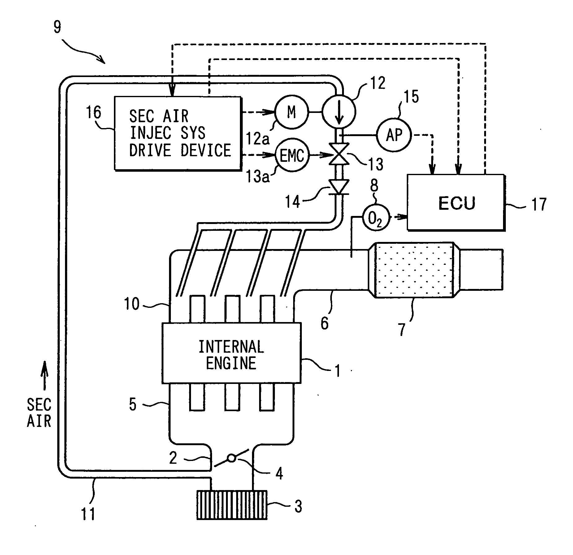
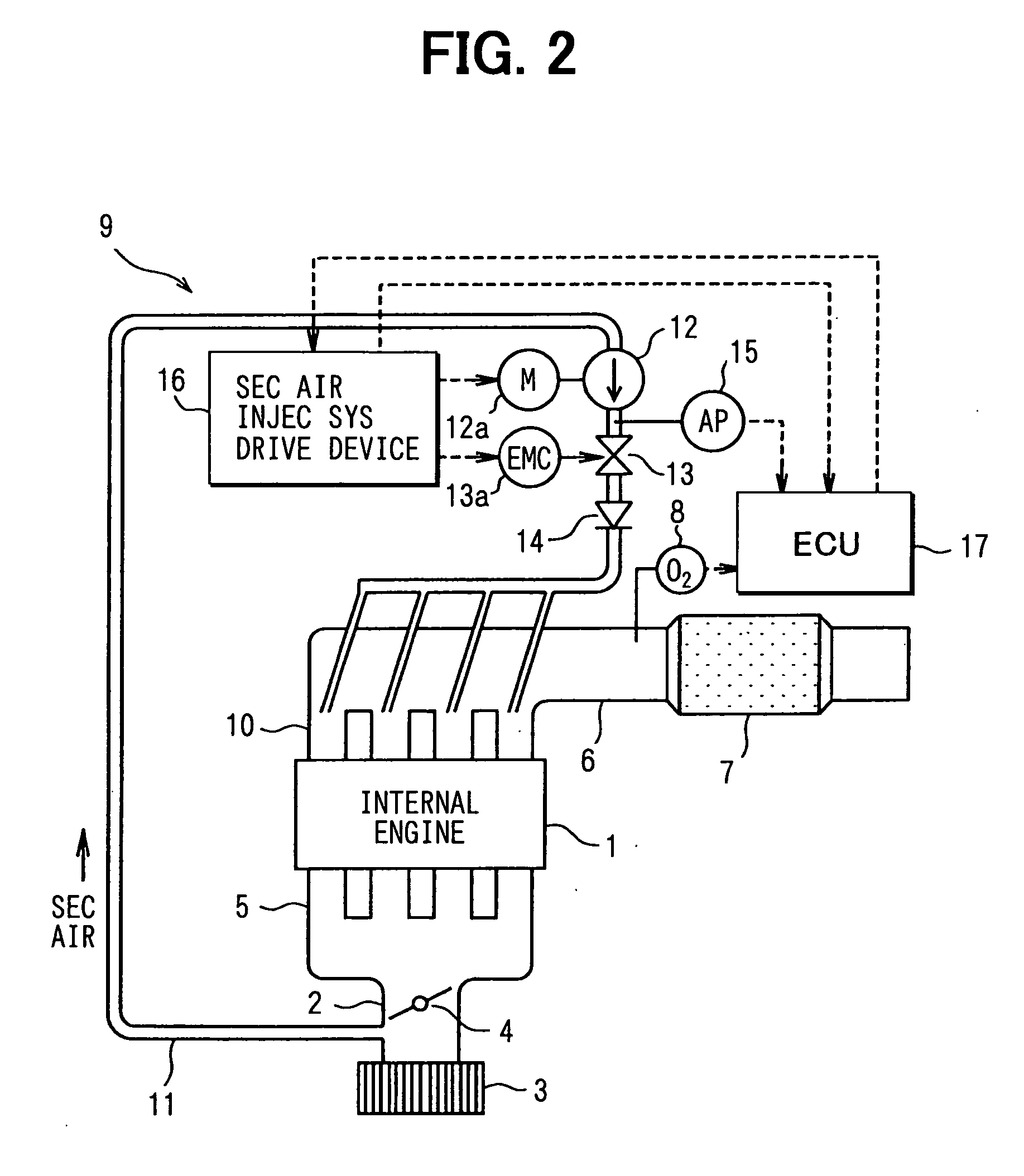
[0027]FIG. 2 schematically illustrates the secondary air injection system. In FIG. 2, an air filter 3 is provided at the most upstream portion of the intake pipe 2 of a multi-cylinder gasoline engine which is an internal combustion engine (hereinafter abbreviated as an engine), and a throttle valve 4 is provided downstream of the intake pipe 2. Though not shown for ease of illustration, fuel injectors are provided near the intake ports of the intake manifold 5 of the engine 1.

[0028] In the exhaust pipe 6 (corresponds to the exhaust gas passage) of the engine 1, a three-way catalyst (hereinafter abbreviated as catalyst) 7 is disposed for purifying the exhaust gas, and an O2 sensor 8 is provided on the upstream side of the catalyst 7 for detecting the concentration of oxygen in the exhaust gas.

[0029] A secondary air feeding device 9 has a secondary air feeding pipe 11 for connecting a po...

second embodiment

[0067]FIG. 4 illustrates a second embodiment, and described below are only those portions different from those of the above first embodiment. This embodiment corresponds to the ninth aspect.

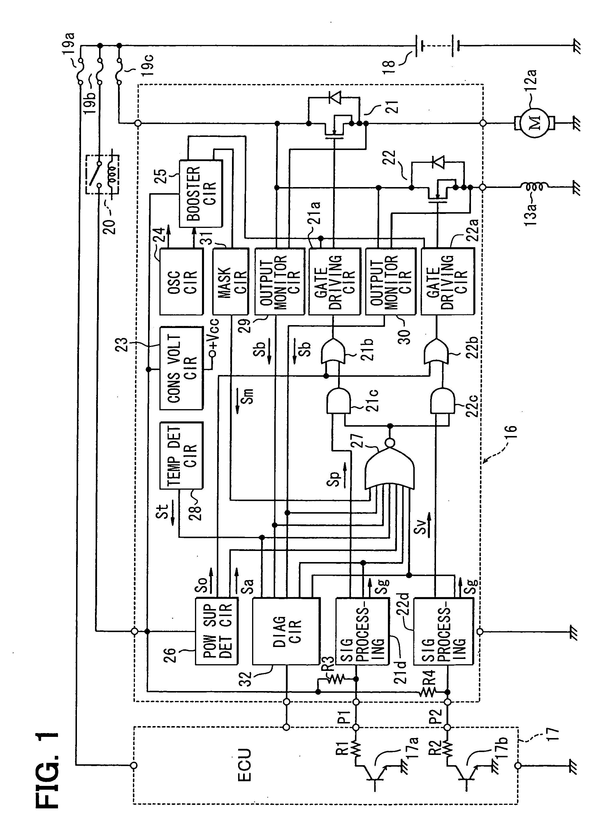
[0068] In FIG. 4, the gate drive circuit 21a is connected between the booster circuit 25 (see FIG. 1) and the grounding terminal, and a gate signal is given to the gate of the MOSFET 21 for driving the motor 12a through a resistor 35. Between the gate and the source of the MOSFET 21, there is connected a series circuit of an npn-type bipolar transistor 36 (corresponds to an auxiliary semiconductor switching element) and a diode 37 of a polarity shown for compensating a breakdown voltage across the collector and emitter and across the base and emitter of the transistor 36. The base of the transistor 36 is connected, via a resistor 38, to a signal line (ground line) connecting the gate drive circuit 21a to the grounding terminal.

[0069] According to this constitution, in case the ground line is br...

third embodiment

[0070]FIGS. 5 and 6 illustrate a third embodiment of the invention which is an improvement of the above second embodiment, and described below are only those portions different from those of the above first and second embodiments. This embodiment corresponds to the invention of the tenth and eleventh aspects of the invention.

[0071]FIG. 5 illustrates the circuit constitution shown in FIG. 4 to which are further added the concrete circuit constitution of the input signal processing circuit 21d of FIG. 1 and the peripheral circuit on the input side thereof. In FIG. 5, the input signal processing circuit 21d includes two comparators 39 and 40 served with a power supply from the power source terminal +VB and the grounding terminal which are for the drive device for the secondary air injection system 16 (see FIG. 1), and a voltage-dividing circuit 41 constituted by connecting the resistors 41a to 41c in series between the power source terminal +VB and the grounding terminal. The comparat...


PUM


Abstract

In a secondary air injection system, MOSFETs control supply of electric current to an air pump and to a motor for driving an electromagnetic valve and to an electromagnetic coil to introduce secondary air into an exhaust gas passage upstream of a catalyst for purifying the exhaust gas of an internal combustion engine. Gate drive circuits control the MOSFETs based on an instruction from an ECU via input signal processing circuits. Abnormal conditions in the operation for controlling the air pump and the electromagnetic valve are detected, and, when an abnormal condition is detected, forcibly turn the MOSFETs off to interrupt the current to the motor and to the electromagnetic coil. A diagnosing circuit sends to the ECU diagnosis signals representing the state of controlling the load.

Description

CROSS REFERENCE TO RELATED APPLICATIONS [0001] This application is based upon, claims the benefit of priority of, and incorporates by reference the contents of, Japanese Patent Application No. 2004-89196 filed on Mar. 25, 2004 and Japanese Patent Application No. 2004-212928 filed on Jul. 21, 2004. FIELD OF THE INVENTION [0002] The present invention relates to a drive device for driving a secondary air injection system to promote the rise of temperature of a catalyst to purify the exhaust gas of an internal combustion engine. BACKGROUND OF THE INVENTION [0003] An internal combustion engine includes a catalyst disposed in its exhaust gas passage for purifying exhaust gas. However, the catalysts may not be capable of sufficiently purifying the exhaust gas when the temperature in the exhaust gas is not sufficiently high during, for example, the cold start of the internal combustion engine. Therefore, a secondary air injection system has been proposed in which secondary air is introduced...

Claims


Application Information

Patent Timeline
IPC IPC(8): F02D43/00F01N3/00F01N3/10F01N3/22F01N3/32F01N3/34F01N11/00F02D41/22F02D45/00F02K99/00F02M33/02
CPCF01N3/22F01N3/32F01N11/00Y02T10/47F02D2041/2075Y02T10/40Y02T10/20F02D41/221Y02T10/12
Inventor ITO, MAKOTOANDO, AKIRATAKEUCHI, SHIGERU
Owner DENSO CORP
Why Eureka
Try Eureka