
Duplex stainless steel and manufacturing method thereof

Active Publication Date: 2005-09-29
NIPPON STEEL CORP
View PDF2 Cites 28 Cited by
  • Summary
  • Abstract
  • Description
  • Claims
  • Application Information

AI Technical Summary

Benefits of technology

[0017] The present invention has been completed based on the chemical composition of a steel product which is capable of ensuring the performances of a duplex stainless steel; an oxide-based inclusion state capable of significantly improving the pitting resistance, and a production process for attaining increased cleanness.
[0023] According to the present invention, duplex stainless steel having good pitting resistance can be stably obtained. Therefore, duplex stainless steel most suitable for steel pipes, steel plates or the like, such as piping for heat exchange, piping or structures for chemical plant, line pipes, oil well or gas well casing or tubing, or umbilical tubes (control piping for submarine oil field) can be provided.

Problems solved by technology

For example in a corrosion test simulating such a severe condition, an 80° C.-ferric chloride test, sufficient pitting resistance cannot be necessarily obtained even in case of super duplex stainless.
Only the adjustment of the contents of Cr, Mo and N (nitrogen) and further W or the like, is often insufficient for the improvement in pitting resistance.
Further, although the pitting resistance can be somewhat improved by reducing the Mn sulfides in the steel, even in duplex stainless steel similar to the austenitic stainless steel, the pitting cannot be absolutely prevented.

Method used


Image

  • Duplex stainless steel and manufacturing method thereof
  • Duplex stainless steel and manufacturing method thereof
  • Duplex stainless steel and manufacturing method thereof

Examples


example 1

[0089] Each duplex stainless steel having a composition shown in Table 1 (super duplex stainless steel with a pitting resistance index PREW of not less than 40) in which 500 kg was melted in an induction melting furnace, transferred to an AOD furnace, and then refined again therein. At this time, the slag basicity of the reductive stage was set to 2.0. The slag and the molten steel were sampled after the completion of the reductive stage, respectively. The temperature of the molten steel tapped to a ladle was immediately measured by a thermocouple, and the elapsed time up to casting start was measured.

[0090] At this time, the ladle is stationary and killed in a given position without producing vibration until it is lifted up by a ladle crane to start casting. The killing condition is shown in Table 2.

TABLE 1Chemical composition (% by mass, Balance: Fe and impurities)CSiMnPSNiCrMoAlNOCaMgCuBWPREW*0.0110.030.350.0230.00046.3525.022.980.0100.3100.00300.00250.0021——2.0143.13

*PREW = C...

example 2

[0098] Each duplex stainless steel, having a composition shown in Tables 3 and 4 was melted in a 500 kg-induction melting furnace, transferred to an AOD furnace, and secondarily refined therein. At this time, the slag basicity in the reductive stage was variously changed. The slag and the molten steel were sampled after the end of reductive stage and just after the composition minute adjustment after reduction, respectively, and the composition-analyzed by chemical analysis. The temperature of the molten steel tapped to a ladle was immediately measured by a thermocouple, and the time to casting start was then measured.

TABLE 3SteelChemical composition (% by mass, Balance: Fe and impurities)No.CSiMnPSNiCrMoAlN0CaMgCuBW{circle over (3)}10.0200.350.720.0210.00044.5422.503.180.0070.1450.00310.00220.0011———35.3120.0220.331.410.0280.00024.8923.123.220.0120.1580.00290.00050.00210.21——36.2730.0170.190.510.0240.00044.5822.893.170.0090.1750.00300.00110.0018—0.0027—36.1540.0180.390.560.0050.0...


PUM

PropertyMeasurementUnit
Temperatureaaaaaaaaaa
Lengthaaaaaaaaaa
Lengthaaaaaaaaaa

Abstract

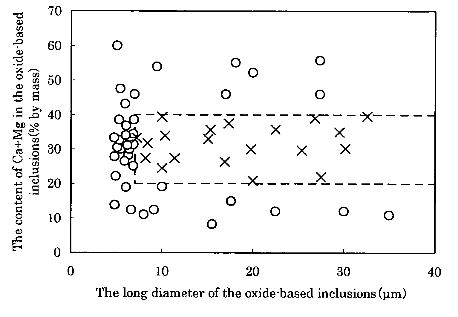
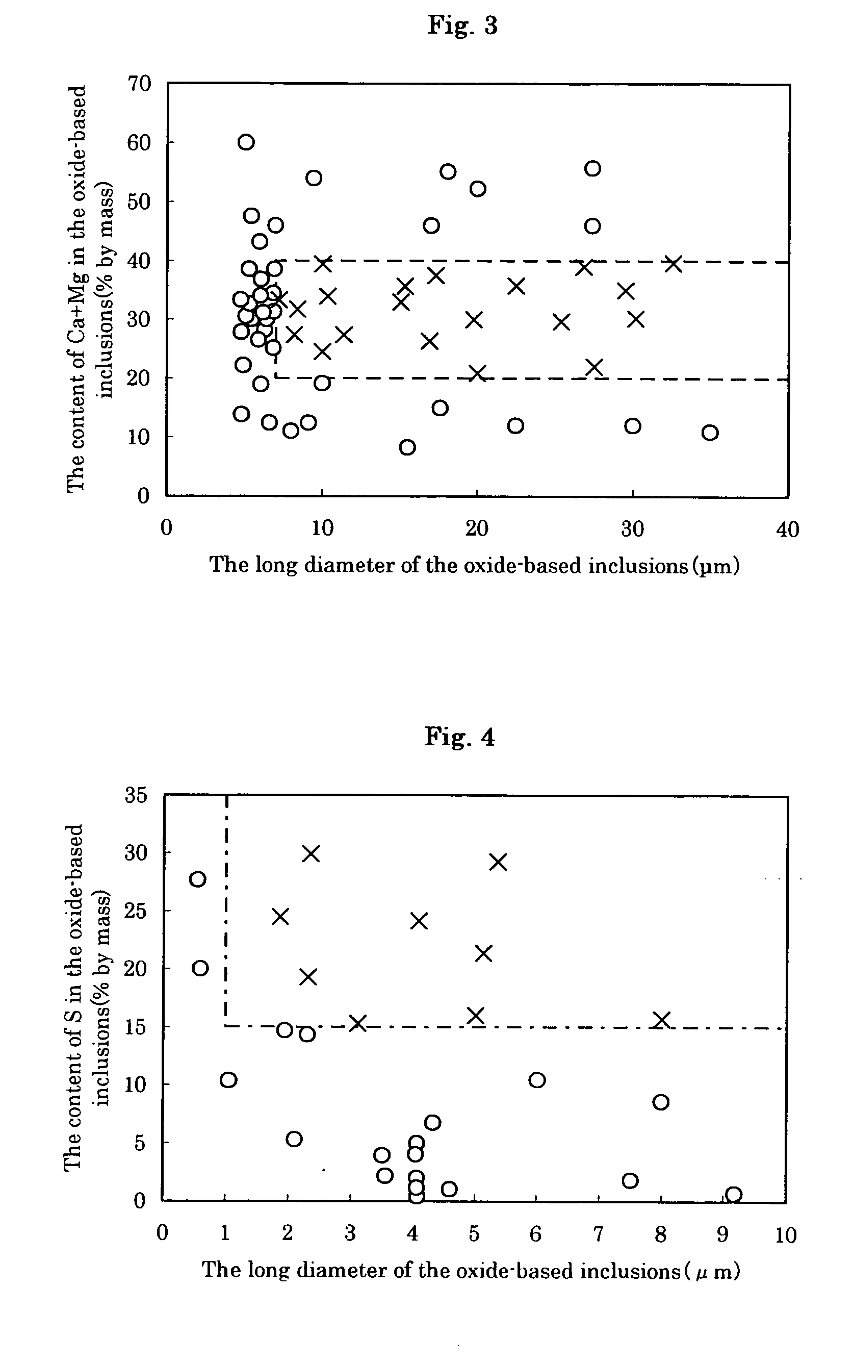
A duplex stainless steel containing C, Si, Mn, P, S, Al, Ni, Cr, Mo, N (nitrogen, O (oxygen), Ca, Mg, Cu, B, and W, and the balance Fe and impurities, where a number of oxide-based inclusions, which have a total content of Ca and Mg of 20 to 40% by mass and also have a long diameter of not less than 7 μm, is not more than a 10 per 1 mm2 of the cross section perpendicular to the working direction, or further, the number of oxide-based inclusions, which have a content of S of not less than 15% by mass and also have a long diameter of not less than 1 μm, is not more than 10 per 0.1 mm2 of the cross section perpendicular to the working direction. Particularly, the contents of Cu, B and W are desirably 0.2 to 2%, 0.001 to 0.01%, and 0.1 to 4% by mass, respectively.

Description

[0001] The disclosure of Japan Patent Application No. 2003-289418 filed Aug. 7th, 2003 including specification, drawings and claims is incorporated herein by reference in its entirety. FIELD OF THE INVENTION [0002] The present invention relates to duplex stainless steel which is excellent in corrosion resistance in seawater. This steel is used for steel pipes, steel plates or the like, such as piping for heat exchange, piping or structures for a chemical plant, line pipes, oil well or gas well casing or tubing, and umbilical tubes (control piping for a submarine oil field). BACKGROUND OF THE INVENTION [0003] Conventionally, although crude oil and natural gas drilled from submarine oil fields and the like have been shunned because of severe working environments, the recent tight energy conditions bring about a situation in which the crude oil and natural gas must be utilized. Therefore, the demand for stainless steel which is excellent in pitting resistance, particularly duplex stain...

Claims


Application Information

Patent Timeline
IPC IPC(8): C22C38/44
CPCC22C33/04C22C38/001C22C38/44C22C38/04C22C38/42C22C38/02
Inventor OMURA, TOMOHIKOMATSUMOTO, SATOSHI
Owner NIPPON STEEL CORP
Learn More