Bottom hole assembly

a technology for assembly and bottom holes, applied in the direction of borehole/well accessories, surveying, drilling pipes, etc., can solve the problems of premature wear and damage of cutters, excessive weight applied to under-reamers, and undesirable bore diameter reductions, etc., to achieve better weight control

Inactive Publication Date: 2005-09-29
SCHLUMBERGER TECH CORP
View PDF14 Cites 57 Cited by
  • Summary
  • Abstract
  • Description
  • Claims
  • Application Information

AI Technical Summary

Benefits of technology

[0008] In a first aspect, the present invention addresses these problems by providing a compliant element between the under-reamer and the drill bit. The compliant element is thus located below the under-reamer. The element can smooth out the transition from one under-reamer / drill bit force distribution to another force distribution, and preferably permits better weight control by either a human or an automated driller.
[0012] Advantageously, the compliant element can reduce shock-loads on the under-reamer. Furthermore, if the under-reamer or drill bit encounters harder material, it can increase the time before the under-reamer or drill bit is damaged or excessively worn by the encounter, thereby providing the driller with an opportunity to take avoiding or mitigating action.
[0015] In normal use down-hole, however, most of the weight is on the drill bit, which shortens the compliant element to a significant extent. When the under-reamer encounters harder material, the weight on the drill bit decreases and the compliant element extends under the influence of the bias. On the other hand, if most of the weight is initially on the under-reamer, the compliant element will extend significantly. Then, when the drill bit encounters harder material, weight which was on the under-reamer transfers to the drill-bit and the compliant element shortens against the influence of the bias.
[0018] The bottom hole assembly may be rotary-steerable. Some such assemblies have thrust members or pads (see e.g. U.S. Pat. No. 6,705,413) which press against the borehole wall and which are particularly vulnerable to shear wave oscillations in the drillstring. Other forms of rotary-steerable system generate a bit deviation without pads contacting the borehole wall, but can also be damaged by back-rotation and excessive rotation speed—both of which can be associated with high levels of bottom hole assembly shear vibration. The shear wave oscillations may be caused by the time lag between a torque increase at the under-reamer when the under-reamer encounters harder material, and the responding torque increase applied by the surface drive system. By providing the compliant element between the drill bit and the under-reamer, such oscillations can be avoided or reduced.
[0019] In preferred embodiments, the bottom hole assembly further has a sensor element which is arranged to measure the weight-on-bit and / or the applied torque of the drill bit, and a transmitter for transmitting the weight-on-bit and / or applied torque measurements to the surface. In principle, surface measurements can provide a driller with preliminary indications as to whether the under-reamer has encountered harder material. However, down-hole measurements provided by the sensor element can confirm these preliminary indications and also provide more accurate measurements of the under-reamer / drill bit force distribution.
[0023] Although the bottom hole assembly of this aspect may not have a compliant element linking the drill bit to the under-reamer, it can still be used by the driller to prevent premature cutter wear or damage.

Problems solved by technology

However, reductions in bore diameter are undesirable as they tend to limit the production flow rate of hydrocarbons through the bore.
However, a problem with BHAs of this type is that if the under-reamer drills material which is much harder than that being drilled by the bit, excessive weight can be applied to the under-reamer.
This can lead to premature wear and cutter damage.
Also, in some circumstances, the opposite problem may occur, i.e. when the bit drills material much harder than that being drilled by the under-reamer, excessive weight can be applied to the bit.
Another problem is that as the material being drilled by the bit and under-reamer changes in hardness, the weight and torque can be transferred very rapidly between the two, leading to axial and rotational shocks.
These shocks may be damaging to down-hole equipment.
The apparatus described in '964, is difficult to adapt to a use with an on-demand under-reamer, as the radial arrangement of central bit drive shaft, prismatic element and circumferential bit does not have the space to accommodate the under-reamer in its retracted position.
Additionally one of the standard methods for under-reamer deployment, the use of a ball drop, would be impossible with the configuration as described.

Method used


Image

  • Bottom hole assembly
  • Bottom hole assembly
  • Bottom hole assembly

Examples


example bha

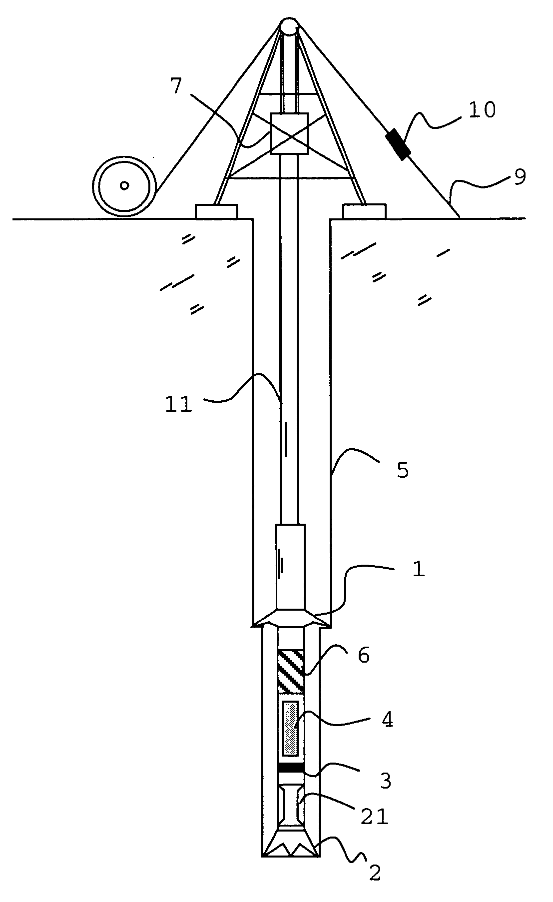
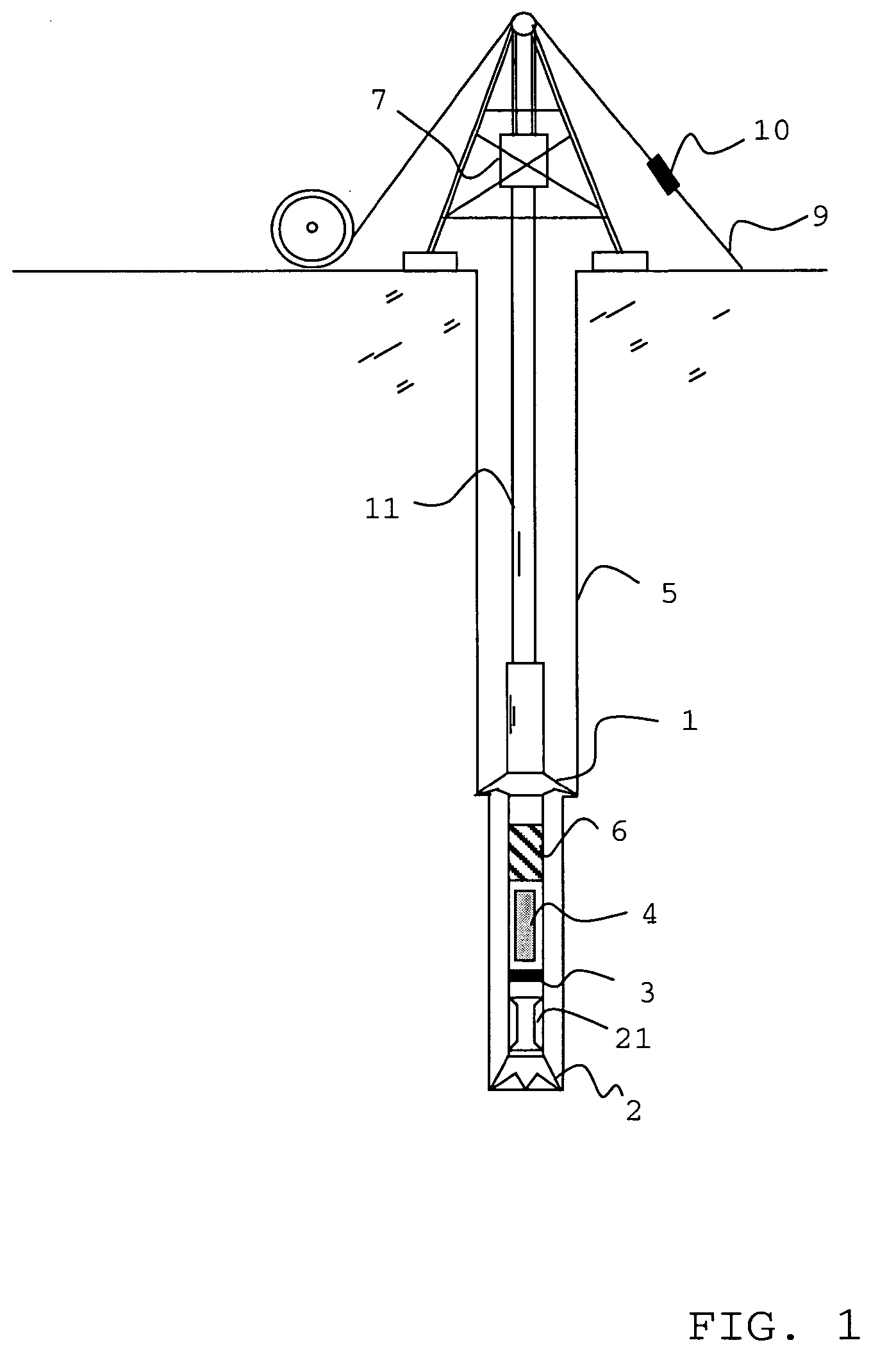
[0061]FIG. 1 shows schematically an apparatus for drilling a bore hole 5. A drill string 11 penetrates the bore hole and terminates at the surface at the top drive 7 of a drilling rig. At the down-hole end of the drillstring, a BHA includes a drill bit 2 and an under-reamer 1 for drilling and enlarging the borehole. The under-reamer has a first diameter when tripping but unfolds to the nominal drilling diameter when in operation.

[0062] A compliant element 6 linking the drill bit to the under-reamer allows the drill bit and under-reamer to move relative to each other in the axial direction of the BHA.

[0063] The compliant element has a stroke length which defines the maximum and minimum axial spacing that can be produced between the drill bit and the under-reamer by this movement. It is biased towards the full stroke position, but the stroke length and compliance of the compliant element are selected such that with normal weight applied to the drill bit, the compliant element is sho...


PUM


Abstract

A bottom hole assembly has a drill bit and an under-reamer on the up-hole side of the drill bit. In one aspect, the assembly further has a compliant element linking the drill bit to the under-reamer, the compliant element allowing displacement of the drill bit relative to the under-reamer in the axial direction of the assembly. In another aspect, the assembly further has a sensor element which is arranged to measure the weight-on-bit and / or the applied torque of the drill bit, and a transmitter for transmitting the weight-on-bit and / or applied torque measurements to the surface.

Description

[0001] The present invention relates to a bottom hole assembly (BHA) having a drill bit and an under-reamer on the up-hole side of the drill bit. BACKGROUND OF THE INVENTION [0002] In drilling operations, such as the drilling of hydrocarbon wells, drilled bores are usually lined with steel tubing known as casing, which is cemented in place by pumping cement into an annulus between the casing and the bore wall. Once a length of casing is in place, this imposes a restriction on the diameter of any subsequent section of bore, as the drill bit and any further casing must pass through the existing casing. However, reductions in bore diameter are undesirable as they tend to limit the production flow rate of hydrocarbons through the bore. Thus under-reamers are used to enlarge such subsequent sections of bore. Examples of under-reamers are disclosed in U.S. Pat. Nos. 6,378,632, 6,615,933, 4,589,504 and 3,712,854. Generally an under-reamer is used in a BHA up-hole of a drill bit. In this wa...

Claims


Application Information

Patent Timeline
Patent Type & Authority Applications(United States)
IPC IPC(8): E21BE21B7/28E21B10/26E21B10/32E21B10/40E21B17/07E21B17/10E21B44/00E21B47/12
CPCE21B10/26E21B44/00E21B17/07E21B10/40E21B17/076E21B7/28E21B17/073
Inventor JEFFRYES, BENJAMIN PETER
Owner SCHLUMBERGER TECH CORP
Why Eureka
Try Eureka