Methods for producing and using catalytic substrates for carbon nanotube growth

a technology of carbon nanotubes and substrates, applied in the field of nanotechnology, can solve the problems of inherently disadvantageous techniques, atomic force microscopy is the size and shape of the scanning probe tip, and the cost of electric arc or laser equipment for solid carbon vaporization is both costly and difficult to operate on commercial or industrial scales

Inactive Publication Date: 2005-09-29
MOLECULAR NANOSYST
View PDF87 Cites 41 Cited by
  • Summary
  • Abstract
  • Description
  • Claims
  • Application Information

AI Technical Summary

Benefits of technology

[0015] A catalyst material is provided for carbon nanotube synthesis. The catalyst material comprises a uniform dispersion of host particles on a substrate, where the host particles include catalyst nanoparticles exposed on the surfaces of the host particles that are effective to catalyze nanotube syntheses reactions. The host particles are formed of a material (a host species) such as aluminum oxide, and the catalyst nanoparticles are formed of a material (a catalyst ...

Problems solved by technology

These techniques are inherently disadvantageous because solid carbon vaporization via electric arc or laser apparatus is both costly and difficult to operate on commercial or industrial scales.
A critical limitation of atomic force microscopy is the size and the shape ...

Method used


Image

  • Methods for producing and using catalytic substrates for carbon nanotube growth
  • Methods for producing and using catalytic substrates for carbon nanotube growth
  • Methods for producing and using catalytic substrates for carbon nanotube growth

Examples


example 1

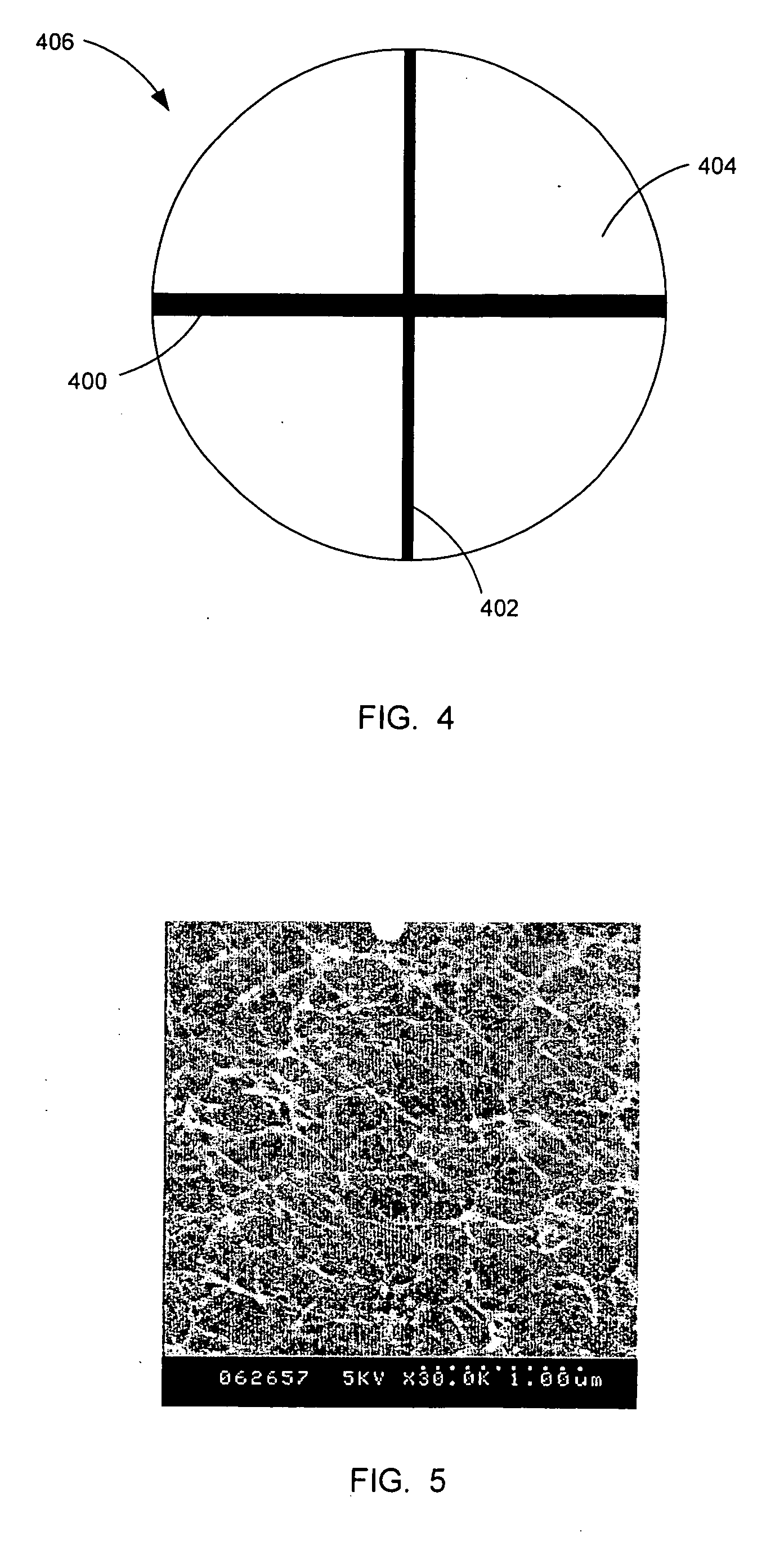
[0057]FIG. 4 is a schematic diagram showing a strip 400 of an Fe foil and a strip 402 of a Mo foil disposed on top of an Al sputtering target 404 with an exemplary diameter of 2.54 cm to form a co-sputtering target 406. In this example the strip 400 of the Fe foil has a width of about 1 mm and the strip 402 of the Mo foil has a width of about 0.5 mm. In one exemplary deposition run, DC sputtering of the co-sputtering target 406 deposited the precursor layer at a rate of 6 nm per minute. Hence, a 3 nm thick precursor layer can be obtained by sputtering for 30 seconds and a 20 nm thick precursor layer can be obtained by sputtering for about 3 minutes. The concentrations of Fe and Mo in the precursor layer are determined by the relative areas of the strips 400, 402 of the co-sputtering target 406.

[0058] After sputtering, the precursor layer can be annealed in air at a temperature in a range from about 400° C. to about 900° C. for a period of time ranging from about 5 to about 30 minut...

example 2

[0060] A 20 nm thick thin film of a Al / Fe / Mo precursor layer was prepared by co-sputtering Al, Fe, Mo in the ratio of 96.1:2.6:1.3 for 3 minutes in a DC sputtering system operating at 50 W power and under a vacuum of 5×10⁻³ mbar. The concentrations of Fe and Mo, 2.6% and 1.3% respectively, were achieved according to the relative areas of Fe and Mo strips 400, 402 in the co-sputtering target 406 of Example 1. The deposited precursor layer was then heated in air at 600° C. for 30 minutes to produce the catalyst material 100. CVD growth of nanotubes under the conditions described in Example 1 on the catalyst material 100 was performed to produce nanotubes as shown in the scanning electron microscope (SEM) micrograph of FIG. 5. This SEM micrograph shows a mat of uniformly distributed and interconnected nanotubes.

example 3

[0061] A patterned catalyst material 100 was prepared by a standard photolithography procedure including spin-coating a photoresist layer on the substrate 106, exposing the photoresist layer through a mask to establish a pattern, and developing the exposed photoresist layer to leave areas of the substrate 106 exposed and other areas covered with the photoresist layer. Next, the catalyst material 100 was deposited according to an embodiment of the invention described above. Finally, the remaining photoresist layer was removed with acetone.

[0062]FIG. 6 shows an AFM image of nanotubes grown from a catalyst material 100 produced from a patterned 20 nm thick Al / Fe / Mo precursor layer. It will be understood that only the right edge of the image in FIG. 6 shows an area in which the catalyst material 100 was patterned, while the remainder of the image shows an area that was protected by the photoresist layer during the deposition of the precursor layer. It can be seen that nanotubes 600 hav...


PUM

PropertyMeasurementUnit
Temperatureaaaaaaaaaa
Dispersion potentialaaaaaaaaaa

Abstract

A catalyst material for carbon nanotube synthesis includes a uniform dispersion of host particles on a substrate. The host particles themselves include catalyst nanoparticles that are effective to catalyze nanotube syntheses reactions and provide nucleation sites. Methods for preparing a catalyst material includes co-sputtering a catalytic species and a host species to directly form the catalyst material. Methods for synthesizing generally aligned nanotubes are also provided. In these methods host particles comprise alumina and the catalyst nanoparticles comprise iron. Also in these methods nanotube synthesis is achieved in an atmosphere including a carbon-containing gas and water vapor.

Description

CROSS-REFERENCE TO RELATED APPLICATIONS [0001] This application is a continuation-in-part of U.S. patent application Ser. No. 10 / 943,321 filed Sep. 16, 2004, titled “Methods for Producing and Using Catalytic Substrates for Carbon Nanotube Growth” which claims the benefit of U.S. Provisional Application No. 60 / 503,919 filed Sep. 17, 2003, titled “Method of Controlling Carbon Nanotube Growth.”STATEMENT REGARDING FEDERALLY SPONSORED RESEARCH OR DEVELOPMENT [0002] This invention was made with United States Government support under National Science Foundation Award No. 0422198 and under Cooperative Agreement No. 70NANB2H3030 awarded by the Department of Commerce's National Institute of Standards and Technology. The United States has certain rights in the invention.BACKGROUND OF THE INVENTION [0003] 1. Field of the Invention [0004] The present invention relates generally to the field of nanotechnology and more particularly substrates for catalyzing the growth of carbon nanotubes, methods ...

Claims


Application Information

Patent Timeline
IPC IPC(8): B01J23/00B01J23/745B01J23/881B01J37/02B01J37/08C01B31/02D01F9/12
CPCB01J23/24B01J23/74B01J23/745B01J23/85B01J23/881C01B31/0233B01J37/08B01J37/14B01J37/347B82Y30/00B82Y40/00B01J37/0238D01F9/1272D01F9/1273C01B32/162
Inventor GU, GANGPAN, LAWRENCE
Owner MOLECULAR NANOSYST
Why Eureka
Try Eureka