Honeycomb structural body

a honeycomb structure and honeycomb technology, applied in the field of honeycomb structure, can solve the problems of insufficient performance, inability to obtain sufficient performance, and large increase in thermal capacity and pressure loss, so as to achieve large compression strength, high purification performance, and large change in density of partition walls

Active Publication Date: 2005-09-29
NGK INSULATORS LTD
View PDF9 Cites 19 Cited by
  • Summary
  • Abstract
  • Description
  • Claims
  • Application Information

AI Technical Summary

Benefits of technology

[0018] As described above, in the present invention, the structure, which relates to the compression strength such as the partition wall thickness, the partition wall density, the cell density, and the like, is changed in the unit of the honeycomb segments constituting the honeycomb structure in stead of simply composing the outer periphery of the honeycomb structure having large compression strength. Accordingly, the respective portions of the honeycomb structure can be easily composed of a different material, thereby the density of the partition walls can be greatly changed. Likewise, in the honeycomb structure, the partition walls are not deformed at all even if the partition wall thickness and the cell density are greatly changed.
[0019] Further, in the present invention, the partition wall thickness, the partition wall density, the cell de

Problems solved by technology

At the time, a problem arises in that cracks and the like are liable to occur in the honeycomb structure in a relatively short time of use because the thermal stress of the honeycomb structure is locally increased due to a difference of thermal expansion among respective portions thereof.
However, any countermeasure is not taken into consideration to prevent breakages which selectively occur in particular portions of the so-called segment type honeycomb structure composed of a plurality of segments joined to each other when the honeycomb structure is used in a case by being gripped therein.
Accordingly, when the honeycomb structure is mounted, a sufficient performance cannot be necessarily obtained.
With this arrangement, a thermal capacity and a pressure loss are greatly increased or a trapping efficiency is greatly reduced.
Accordingly, a high pu

Method used


Image

  • Honeycomb structural body
  • Honeycomb structural body
  • Honeycomb structural body

Examples


example 1

[0057] Mixed powder containing 75% by weight of SiC powder and 25% by weight of metal Si powder was prepared as a ceramic material. 6 parts by weight a binder, which was composed of methyl cellulose and hydroxypropoxyl methyl cellulose, 0.8 part by weight of a surface-active agent, and 22 parts by weight of water were added to 100 parts by weight of the resultant blended powder. The resultant was kneaded in a kneading machine, thereby a clay having plasticity was obtained.

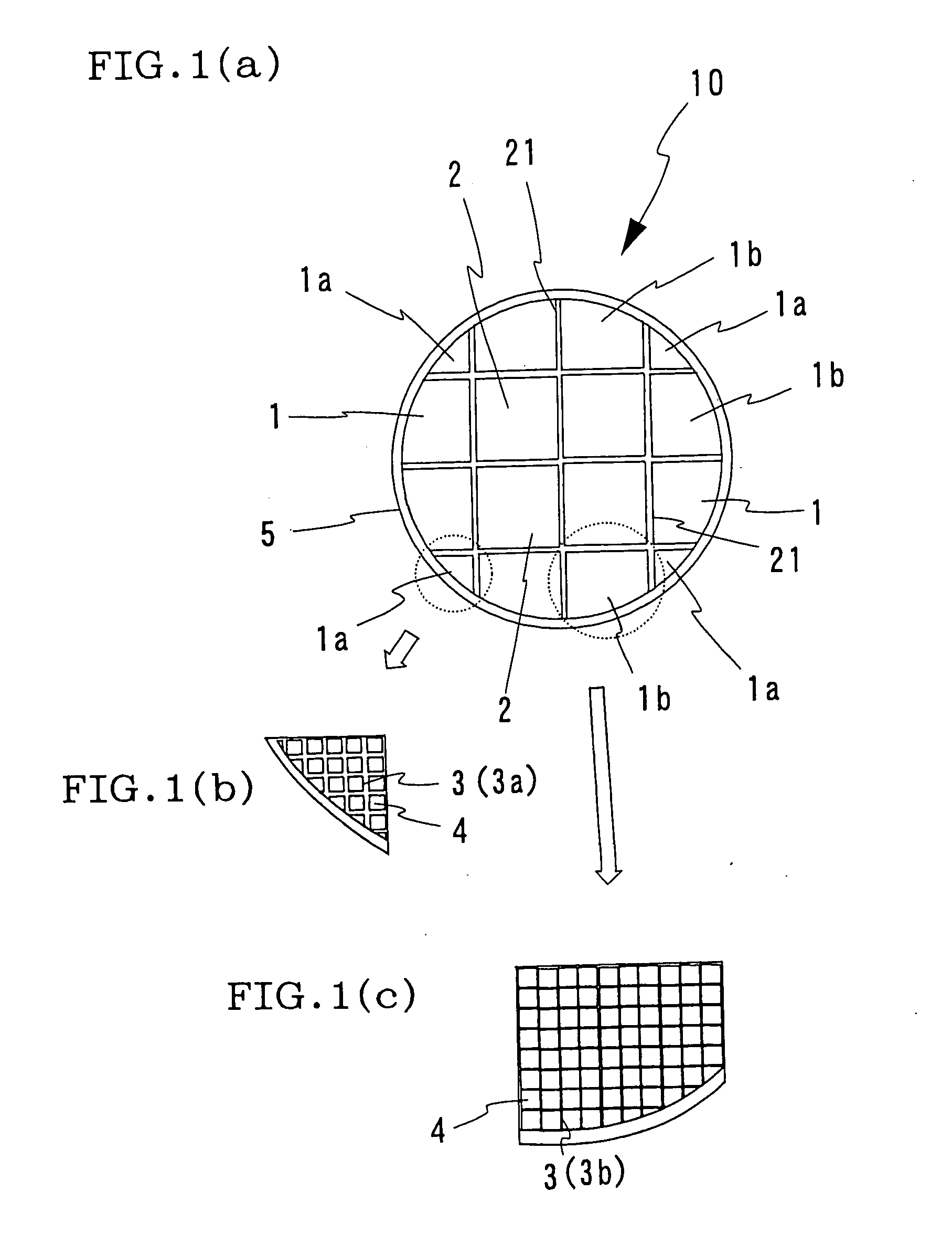
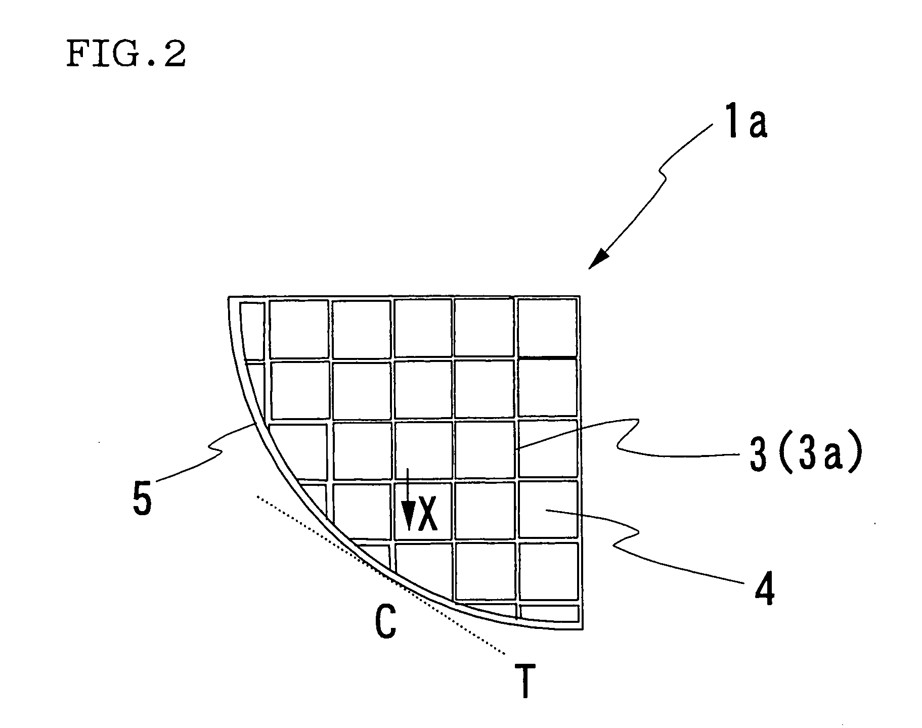
[0058] Next, the clay was subjected to extrusion forming to form the honeycomb segments 1a, 1b, and 2 having shapes corresponding to the shapes of the respective pieces of 16 portions obtained by dividing the honeycomb structure 10 having an cylindrical outside appearance as shown in FIGS. 1(a) and 2. At the time, in all the four honeycomb segments 1a in which the partition walls in the partition wall length direction X on a cross section perpendicular to the fluid passage direction of a cell formed an angle of 20...


PUM

PropertyMeasurementUnit
Angleaaaaaaaaaa
Angleaaaaaaaaaa
Angleaaaaaaaaaa

Abstract

Disclosed is a honeycomb structure 10 made by joining a plurality of honeycomb segments 1, 2 in each of which a plurality of cells each having a rectangular sectional shape are formed between partition walls 3 which are at right angles to each other. At least a portion of the honeycomb segments 1 constituting the outer periphery 5 of the honeycomb structure 10 has a structure in which compression strength is larger than that of the honeycomb segments 2 constituting the other portions of the honeycomb structure 10.

Description

TECHNICAL FIELD [0001] The present invention relates to a honeycomb structure. More specifically, the present invention relates to a honeycomb structure composed of a combination of a plurality of honeycomb segments. BACKGROUND ART [0002] Ceramic honeycomb structures are actively used in various applications such as a catalyst carrier applied to combustion equipment such as a boiler and the like, internal combustion engines such as a diesel engine and the like, a chemical reactor, a reformer for fuel cell and the like, or a filter for trapping and removing particulate matters contained in exhaust gases, by making use of the characteristics of ceramic quality excellent in heat resistance. [0003] Although these honeycomb structures are installed in a case with the outer peripheral side thereof gripped, they are often installed in such a manner that the outer peripheral side thereof is gripped with a large force as in a case that they are installed in the vicinity of an engine which is...

Claims


Application Information

Patent Timeline
IPC IPC(8): F01N3/02B01D39/20B01D46/00B01D46/24B01D53/88B01J35/04B28B1/00C04B38/00F01N3/022F01N3/28
CPCB01D39/2068Y10T428/24149B01D46/2429B01D46/2451B01D46/2459B01D46/2466B01D46/247B01D46/2474B01D53/885B01D2046/2433B01D2046/2477B01D2046/2496B01J35/04B28B1/002C04B38/0006F01N3/0222F01N3/281F01N3/2828F01N2330/30F01N2450/28B01D46/2425Y02T10/20C04B38/008Y02T10/12B01D46/24491B01D46/2498B01D46/2488B01D46/2484B01D46/2478B01D39/20B01D46/00F01N3/02B01D46/249B01D46/2455
Inventor SAKAMOTO, HIROFUMI
Owner NGK INSULATORS LTD
Why Eureka
Try Eureka