Fuel system for internal combustion engine

a fuel system and internal combustion engine technology, applied in the direction of electrolysis components, electrolysis processes, cells, etc., can solve the problems of using hydrogen as a fuel supplement, presenting the same difficulties as its use, and ever present danger of accidental ignition and explosion, so as to reduce or eliminate the buildup of sludge and/or particulates from unwanted side reactions, reduce or eliminate contaminants, and high flow rate

Inactive Publication Date: 2005-10-06
HYDROGEN INNNOVATIONS
View PDF4 Cites 66 Cited by
  • Summary
  • Abstract
  • Description
  • Claims
  • Application Information

AI Technical Summary

Benefits of technology

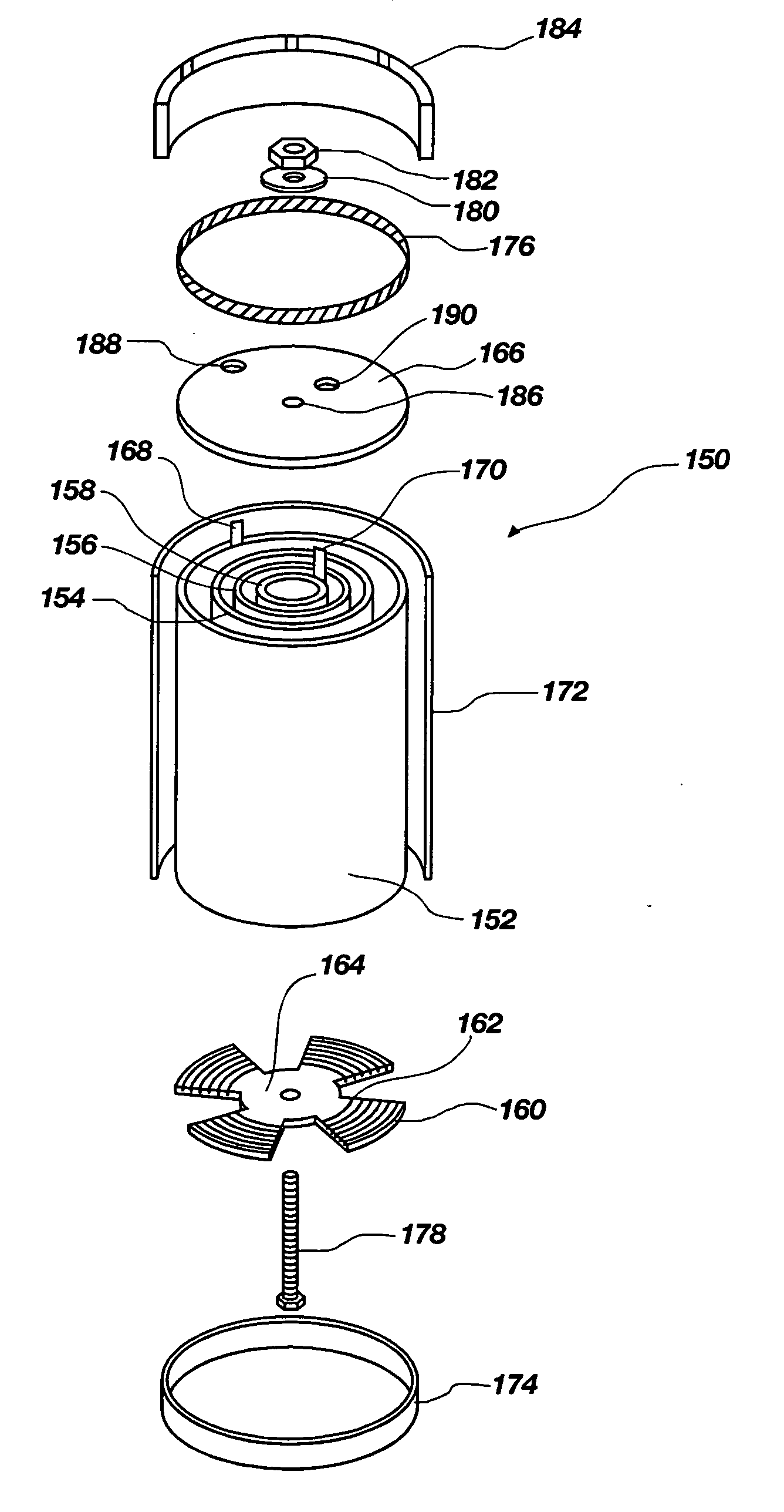
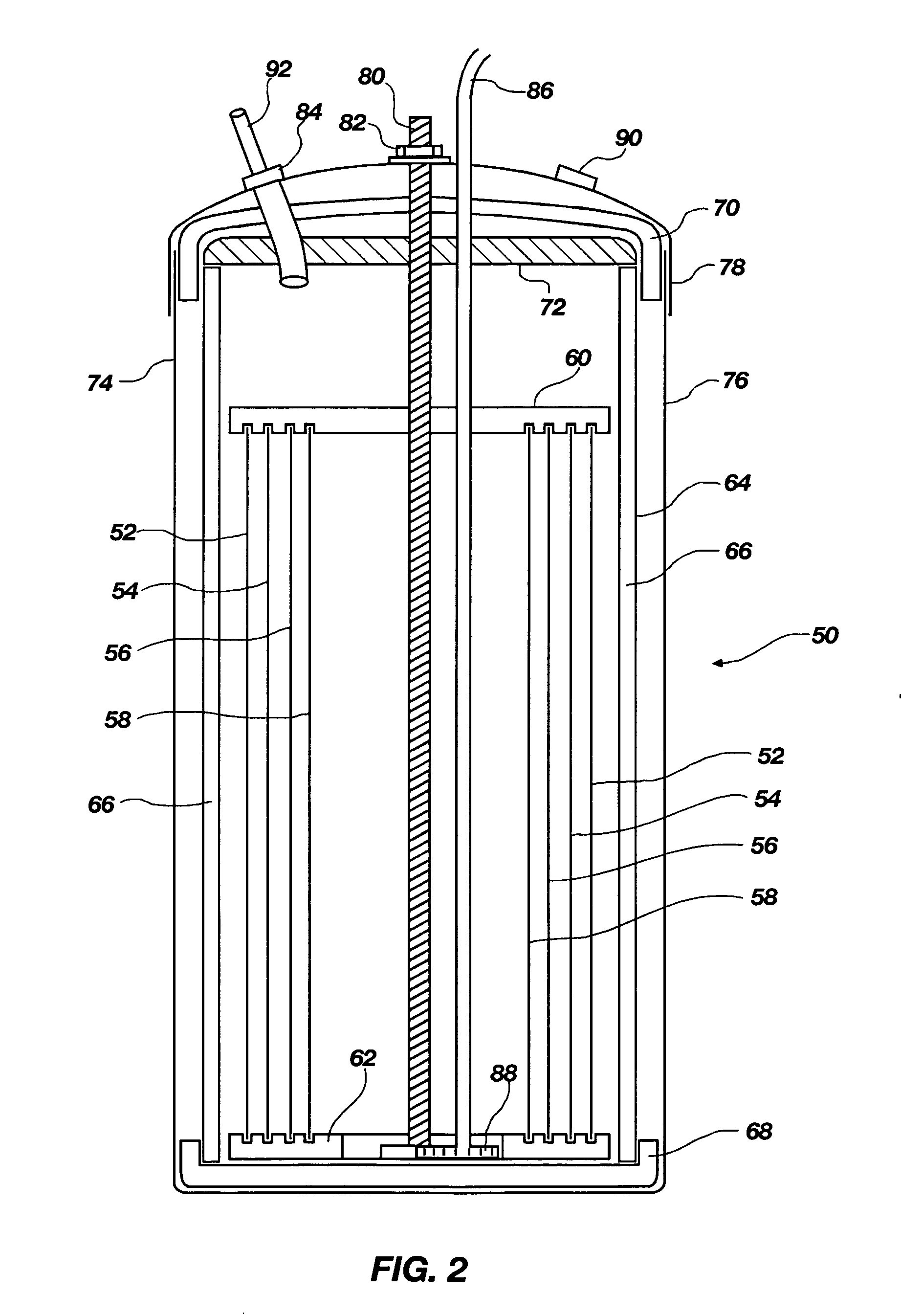
[0014] Another illustrative embodiment of the invention includes an electrode array of a plurality of spaced-apart electrodes for use in this fuel system and a nonconductive support connected to each of the electrodes to hold the electrodes in place, while leaving adequate space around the electrodes to allow free flow of the aqueous electrolyte solution between the electrodes and thereby assist in heating and cooling the aqueous solution of the electrolysis cell of this invention.
[0015] Still another illustrative embodiment of the invention provides an electrode array positioned in a container to allow impurities to settle out and be removed from the container. Also the container may contain a sampling apparatus, which allows samples to be taken from the aqueous electrolyte solution without allowing impurities to enter the vessel.
[0016] Yet another illustrative embodiment of the invention comprises use of a high-purity electrolyte and electrodes and containers that are substantially non-reactive with the electrolyte. These improvements result in production of high flow rates of product gases with little or no sludge formation from side reactions.
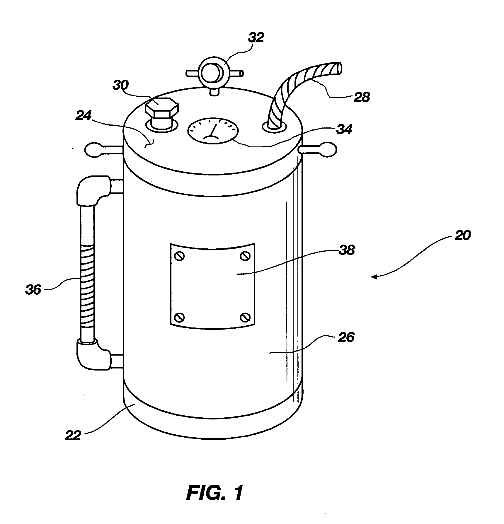
[0017] Still further, an illustrative embodiment of the invention uses a sealable container for holding the electrolysis cell. Sealing of the container reduces or eliminates contaminants from outside the cell from entering the cell, thus reducing or eliminating buildup of sludge and / or particulates from unwanted side reactions. To reduce the danger of pressure buildup in the cell, pressure release mechanisms are built into such a container, such mechanisms including valves and the like.

Problems solved by technology

There are, however, serious drawbacks to the use of hydrogen that have prevented its adoption as a common engine fuel.
Among the most important of its drawbacks is its extreme volatility, creating an ever present danger of accidental ignition and explosion.
The use of hydrogen as a fuel supplement, however, presents the same difficulties as its use as a primary fuel, although on a smaller scale.
While this arrangement has confirmed certain theoretical advantages of hydrogen supplementation, it has, apparently, not yielded a practical, workable system, as the arrangement has been known for some time but has not come into common use.
One of the major problems is that the amounts of hydrogen and oxygen produced in the prior art systems are very low or inconsistent.
Also, the aqueous solutions in the electrolysis cells of the prior art tend to have very short lives and the solution has to be changed often.
This contamination of the solution also causes fouling of the electrodes, which causes further delays and problems to clean or replace the electrodes and auxiliary equipment.
Prior art systems also have had heating problems, which have caused numerous shutdowns or cutting back on the current to the electrolysis cell, thus causing a decrease in production of hydrogen and oxygen that can be utilized by the engine.
However, these teachings do not address the real problem faced by those who use vehicles in long trips where both heating and cooling are real problems that must be addressed to get consistent, high production without mechanical problems caused by lack of temperature control.

Method used


Image

  • Fuel system for internal combustion engine
  • Fuel system for internal combustion engine
  • Fuel system for internal combustion engine

Examples


example 1

[0083] A 1998 Chevrolet ½-ton pickup truck with a 5.7-liter gasoline engine and automatic transmission was tested prior to installation of a fuel system according to the present invention and was determined to produce a maximum of 169 horsepower and 293 ft.-lbs. of torque. An emissions test was performed on this vehicle, wherein a passing score of 33 parts per million (ppm) of hydrocarbons was obtained at 2500 revolutions per minute (rpm). The two catalytic converters were removed from the vehicle, resulting in the “check engine” light on the dashboard coming on, and then the emissions test was repeated, resulting in a failing score of 279 ppm of hydrocarbons.

[0084] Next, an electrolysis fuel system according to the present invention was installed on the vehicle and the emissions and performance tests were repeated. The “check engine” light on the dashboard did not come back on after installation of the electrolysis fuel system. The hydrocarbons level was 32 ppm, which was a passin...

example 2

[0085] A 2003 Chevrolet Duramax diesel pickup truck was tested prior to installation of an electrolysis fuel system according to the present invention. The horsepower rating was 264.0 and the torque registered 450.4 ft-lbs. Upon emissions testing, this vehicle produced a passing score of 9.2% particulates (opacity). After installation of an electrolysis fuel system according to the present invention, the horsepower rating increased to 332.4, an increase of 67.5 horsepower; the torque rating increased to 563.3 ft-lbs, an increase of 112.9 ft-lbs; and the emissions test showed 0% particulates.

example 3

[0086] A 2004 Ford F-250 Powerstroke with a diesel engine was tested prior to installation of an electrolysis fuel system according to the present invention. Without a performance chip, the tests showed 272.6 horsepower and 412.4 ft-lbs of torque. Then, an Edge performance chip was installed and the tests were repeated, resulting in 271.0 horsepower and 416.7 ft-lbs of torque. An electrolysis fuel system according to the present invention was installed and the performance chip was removed, and the tests were again repeated, resulting in 275.8 horsepower and 434.2 ft-lbs of torque. These results amounted to increases over the stock results of 3.2 horsepower and 21.8 ft-lbs of torque. Finally, the performance chip was reinstalled, and the tests showed results of 279.7 horsepower and 432.7 ft-lbs of torque. These results amounted to increases over the stock results of 7.1 horsepower and 20.3 ft-lbs of torque.


PUM

PropertyMeasurementUnit
temperatureaaaaaaaaaa
pHaaaaaaaaaa

Abstract

A fuel system is provided for generating hydrogen and oxygen for use in an internal combustion engine to improve combustion efficiency, horsepower, and torque and to decrease emissions. The fuel system has at least one electrolysis cell for generating hydrogen and oxygen by electrolysis of an aqueous solution, a power source for providing electrical power to the electrolysis cell, and a heating and cooling system for maintaining the temperature of the electrolysis cell in a desired range to obtain the desired quantities of hydrogen and oxygen for operation of the internal combustion engine. The invention also includes an electrode array of a plurality of spaced apart electrodes for use in this fuel system and a nonconductive support connected to each of the electrodes to hold the electrodes in place, while leaving adequate room around the electrodes to allow free flow of the aqueous solution between the electrodes. High purity electrolyte and substantially non-reactive electrodes result in improved electrolysis.

Description

CROSS-REFERENCE TO RELATED APPLICATIONS [0001] This application claims the benefit of U.S. Provisional Application No. 60 / 542,477, filed Feb. 5, 2004, which is hereby incorporated herein by reference.STATEMENT REGARDING FEDERALLY SPONSORED RESEARCH OR DEVELOPMENT [0002] Not applicable. BACKGROUND OF THE INVENTION [0003] This invention relates to a hydrogen and oxygen generating fuel system for use with an internal combustion engine. More particularly, this invention relates to a hydrogen and oxygen fuel generating system for improving performance of an internal combustion engine. [0004] A major effort has been made to develop fuel systems comprising electrolysis cells for producing hydrogen and oxygen from water to help solve the air pollution and fuel efficiency problems associated with the use of internal combustion engines. [0005] Hydrogen has numerous important advantages as a fuel. The energy released per pound is high when compared to conventional fuels, and hydrogen is clean-...

Claims


Application Information

Patent Timeline
Patent Type & Authority Applications(United States)
IPC IPC(8): C25B9/17C25B15/00
CPCC25B1/04Y02E60/366C25B15/00C25B9/00Y02E60/36
Inventor DAHLQUIST, DAVID F. JR.
Owner HYDROGEN INNNOVATIONS
Why Eureka
Try Eureka