Method and apparatus for selective pre-dispersion of extracted ion beams in ion implantation systems

a selective pre-dispersion and ion beam technology, applied in electrical equipment, nuclear engineering, electric discharge tubes, etc., can solve the problem of limiting the effect of space charge expansion that results from the entire extracted beam, and achieve the effect of mitigating the space charge

Inactive Publication Date: 2005-10-06
AXCELIS TECHNOLOGIES
View PDF7 Cites 12 Cited by
  • Summary
  • Abstract
  • Description
  • Claims
  • Application Information

AI Technical Summary

Benefits of technology

[0012] The present invention is related to ion implantation systems and methods in which a dispersion system or pre-disperser is provided near the ion source at the beamline assembly entrance, to selectively pass the extracted ion beam from the source to the mass analyzer or to pre-disperse the extracted beam to form a dispersed beam with fewer of the undesired mass constituents that is then directed to the mass analyzer. The dispersion apparatus and methodologies of the invention can be employed in any type of ion implantation system, including high energy implanters having post-mass analysis acceleration components as well as in low energy implanters. The various aspects of the invention may be employed to mitigate space charge effects in transporting low energy ion beams from an ion source to a general purpose mass analyzer designed for a wide range of ion beam energies, through selective removal of ions of undesired mass from the extracted beam, thereby reducing the beam current prior to the main mass analyzer, while allowing higher energy beams to be provided directly to the primary mass analyzer without pre-dispersion.
[0013] In one aspect of the invention, an ion implantation system is provided, comprising an ion source to produce an extracted ion beam, a dispersion system located near the ion source to receive the extracted ion beam, a mass analyzer receiving either the extracted ion beam or a dispersed ion beam from the dispersion system, and an end station located downstream from the mass analyzer. The dispersion system selectively passes the extracted ion beam from the ion source toward the mass analyzer or directs a dispersed ion beam toward the mass analyzer having fewer ions of an undesired mass range than the extracted ion beam. Because the dispersion system is used only with low energy extracted ion beams, it can be devised to perform the dispersion in a very short distance, thus limiting the effect of space charge expansion that results from the entire extracted beam. In the exemplary implementations illustrated and described below, the dispersion system comprises a plurality of magnets providing dipole magnetic fields near the beamline assembly entrance to selectively direct the extracted beam to a resolving structure that intercepts ions of undesired mass and passes ions of a desired mass to the main mass analyzer. The dispersion system magnets in one example are configured to direct the extracted beam through a double dog-leg path that includes the resolving structure, and the dispersed beam is redirected toward the main mass analyzer along the original extracted beam path. In another implementation, the dispersion system selectively redirects the extracted beam along a single dog-leg path for dispersion, wherein the dispersed beam is provided to the main mass analyzer along a second path.

Problems solved by technology

Because the dispersion system is used only with low energy extracted ion beams, it can be devised to perform the dispersion in a very short distance, thus limiting the effect of space charge expansion that results from the entire extracted beam.

Method used


Image

  • Method and apparatus for selective pre-dispersion of extracted ion beams in ion implantation systems
  • Method and apparatus for selective pre-dispersion of extracted ion beams in ion implantation systems
  • Method and apparatus for selective pre-dispersion of extracted ion beams in ion implantation systems

Examples


Embodiment Construction

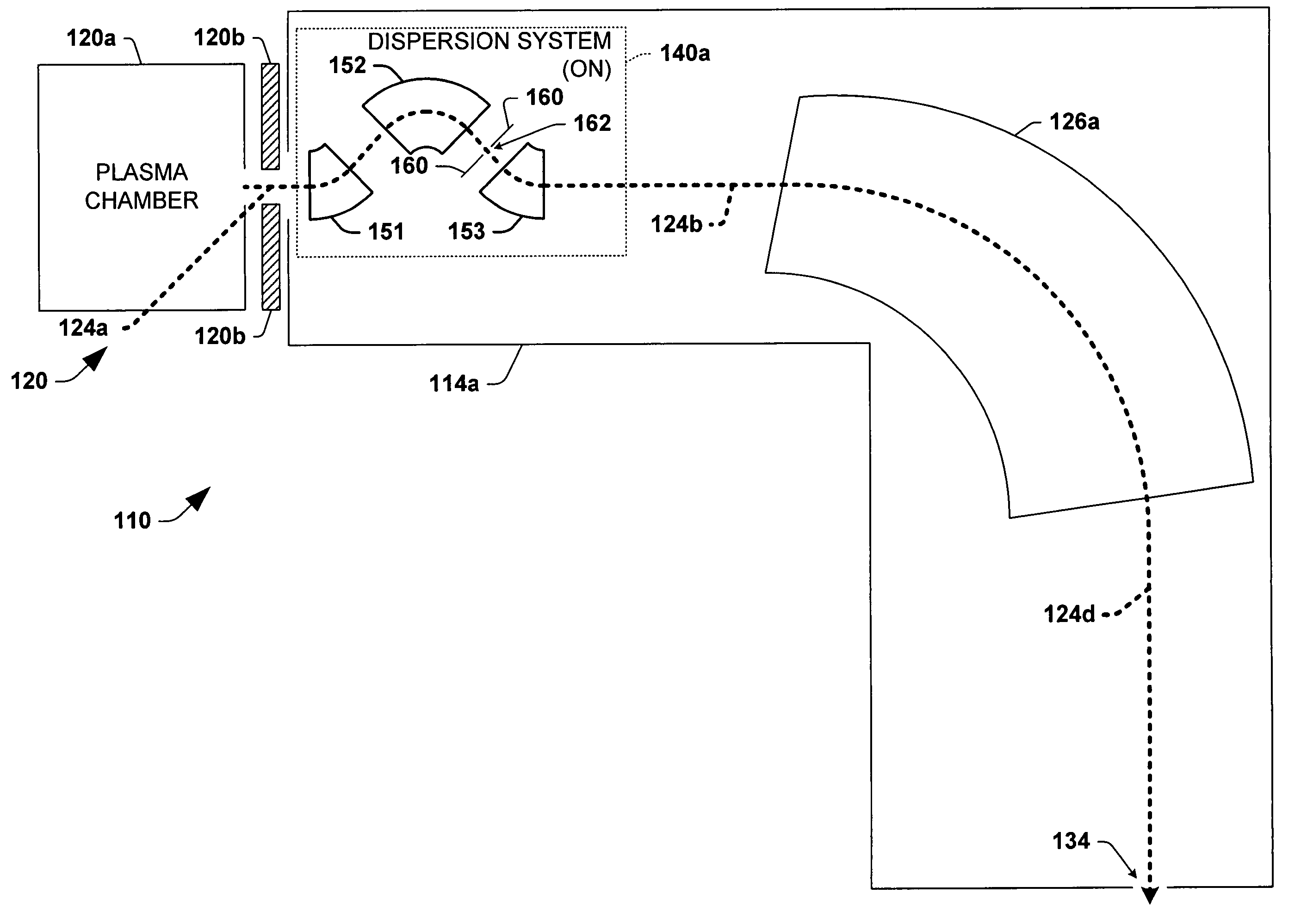
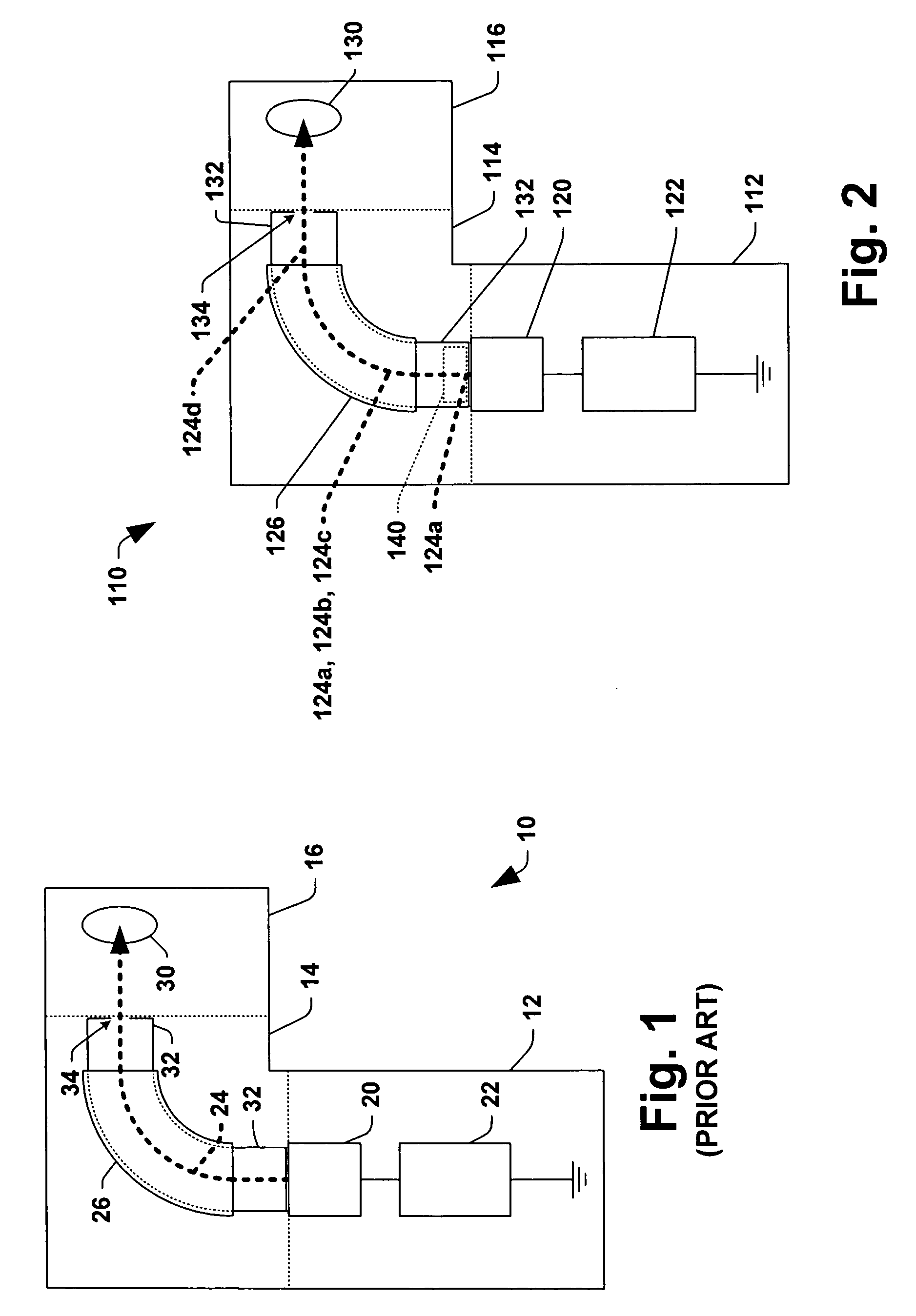
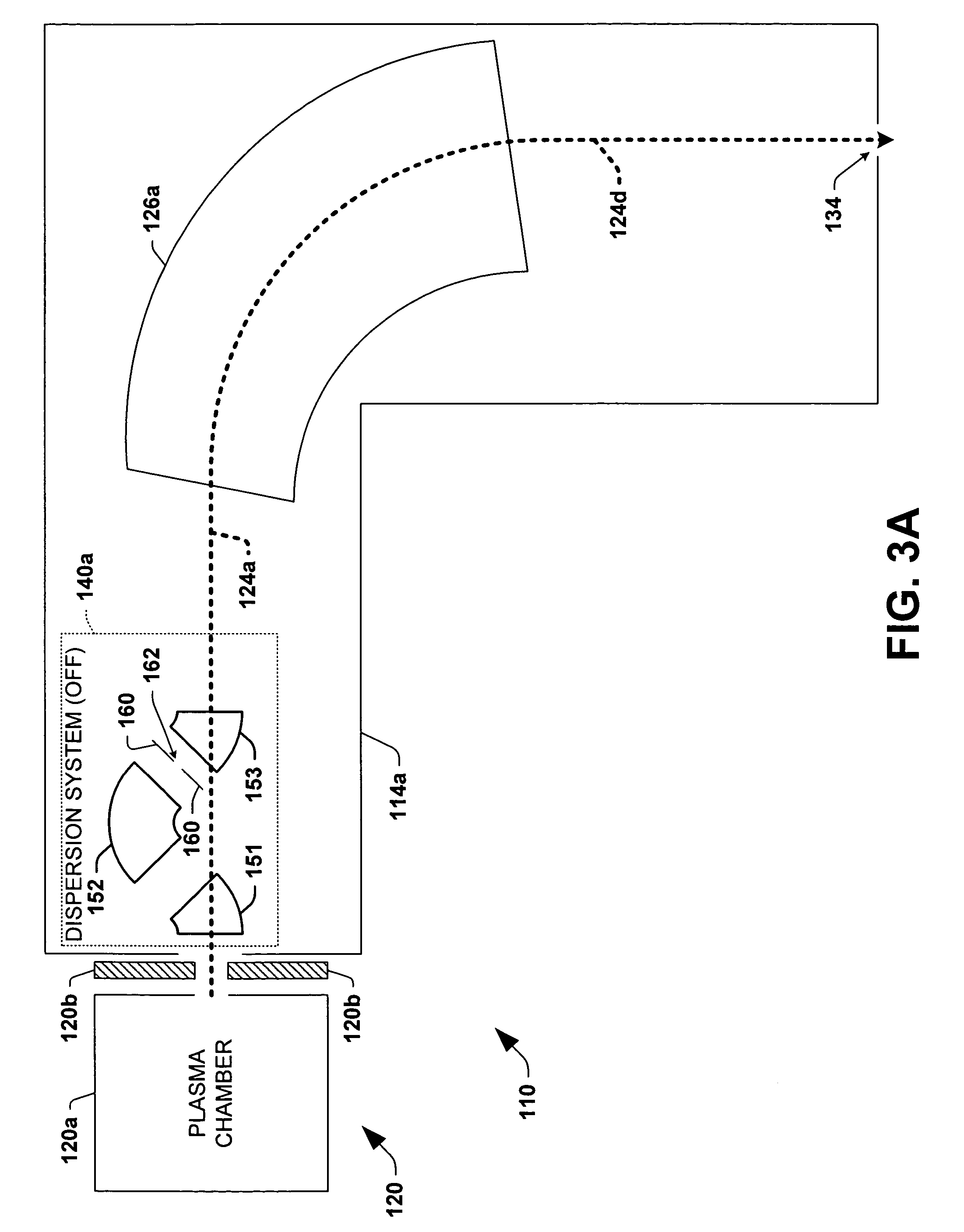
[0026] The present invention will now be described with reference to the drawings wherein like reference numerals are used to refer to like elements throughout, and wherein the illustrated structures are not necessarily drawn to scale. The present invention provides ion implantation systems and beamline assemblies therefor, having dispersion systems that selectively pre-disperse low energy beams prior to a main mass analyzer to facilitate beam transfer without beam blowup, and also to allow passage of higher energy beams directly to the main mass analyzer. Several examples of low energy implantation systems and beamline assemblies therefor are hereinafter presented in order to illustrate the various aspects of the invention. However, it will be appreciated that the invention may be advantageously employed in ion implanter systems apart from those illustrated and described herein, including high energy implanters having acceleration components.

[0027]FIG. 2 illustrates an exemplary i...


PUM


Abstract

Ion implantation systems are provided, comprising a dispersion system located between an ion source and a mass analyzer, that operates to selectively pass an extracted ion beam from the ion source toward the mass analyzer or to direct a dispersed ion beam toward the mass analyzer, where the dispersed ion beam has fewer ions of an undesired mass range than the extracted ion beam.

Description

FIELD OF THE INVENTION [0001] The present invention relates generally to ion implantation systems, and more specifically to improved methods and apparatus for selectively pre-dispersing extracted ion beams in an ion implantation system. BACKGROUND OF THE INVENTION [0002] In the manufacture of semiconductor devices, ion implantation is used to dope semiconductor wafers with impurities. Ion implanters or ion implantation systems treat semiconductor wafers with an ion beam, to produce n or p-type doped regions or to form passivation layers in the wafers during fabrication of integrated circuits. When used for doping semiconductors, the ion implantation system injects a selected ion species to produce the desired extrinsic material. Implanting ions generated from source materials such as antimony, arsenic or phosphorus results in n type extrinsic material wafers, whereas if p type extrinsic material wafers are desired, ions generated with source materials such as boron, gallium or indiu...

Claims


Application Information

Patent Timeline
Patent Type & Authority Applications(United States)
IPC IPC(8): H01J37/05H01J37/317
CPCH01J37/3171H01J37/05
Inventor BENVENISTE, VICTOR M.
Owner AXCELIS TECHNOLOGIES
Why Eureka
Try Eureka