Separator and fuel cell using thereof

a fuel cell and separator technology, applied in the direction of cell components, cell component details, electrochemical generators, etc., can solve the problems of inability to obtain desired power generation performance, difficulty in obtaining fluid passages having desired depths and widths, and inability to uniformly react gas streams, etc., to achieve long use life, reduce costs, and reduce costs

Inactive Publication Date: 2005-10-06
HITACHI LTD
View PDF5 Cites 28 Cited by
  • Summary
  • Abstract
  • Description
  • Claims
  • Application Information

AI Technical Summary

Benefits of technology

[0014] According to the present invention, there is provided a separator which can be easily fabricated and assembled with a lower internal voltage drop and less performance deterioration, and there is provided a fuel cell using this separator. Further, since the above-mentioned components can be simply prepared by mere drilling, and are planar as they are, a contact area therebetween and a contact area thereof with another component can be larger.
[0028] Further, the covered metal is formed therein with a slit which allows the passage boards which are located on opposite sides of the cover metal panel, to make electrical contact with one another while no metal is present in the running path of a current. Thus, it is possible to eliminate such a serious problem that the contact resistance is increased due to the growth of a nonconductive film and corrosion which are caused in use of metal as a material of the separator (Embodiment 1). Further, since no adhesion is required, the manufacturing process can be simplified. In the separator formed of a metal planar panel and conductive passage boards, the metal planar panel is formed therein with a plurality of manifolds for passing reactive fluid or cooling medium through an adjacent cell.

Problems solved by technology

However, in the case of a separator made of metal, should a thin sheet metal be formed therein with passage channels by pressing, it would be difficult to obtain fluid passages having desired depths and widths due to a limitation of workability caused by a process limit to a metal material.
Thus, there would be caused such hindrances as non-uniformity of reaction gas streams, and less area of contact with an electrode.
As a result, there would be caused such a problem that a desired power generating performance cannot be obtained.
Even though a desired channel can be formed, the separator after fabrication would be warped or deformed, or could not have a required degree of finishing accuracy, resulting in leakage of reaction gas or increase in contact resistance.
As another disadvantage caused by the press-formed metal separator, apex tops of channels after fabrication have curvatures, and accordingly, an area of contact with the gas diffusion layer or the like becomes less.
As a result, there would be caused such a problem that the resistance is increased.
In the case of making conventional metal separators in contact with one another, there would be caused such a problem that their contact area cannot be obtained sufficiently.
That is, since the apices of channels for passage of reaction gas, which are defined by spaces between two separators mated with one another, are not flat, the separators are made into line or point contact with one another, and accordingly, the resistance of contact becomes higher, resulting in difficulty in obtaining a satisfactory performance of power generation.
As a result, there have been such problems that the number of components constituting a cell is increased, and that the number of manufacturing steps is increased since the components are fastened to one another by conductive materials.
Thus, there would be caused increase in contact resistance caused by corrosion on the metal side, contamination to electrodes and electrolytic membranes caused by corrosion products, and the like, resulting in deterioration of the fuel cell.

Method used


Image

  • Separator and fuel cell using thereof
  • Separator and fuel cell using thereof
  • Separator and fuel cell using thereof

Examples


embodiment 1

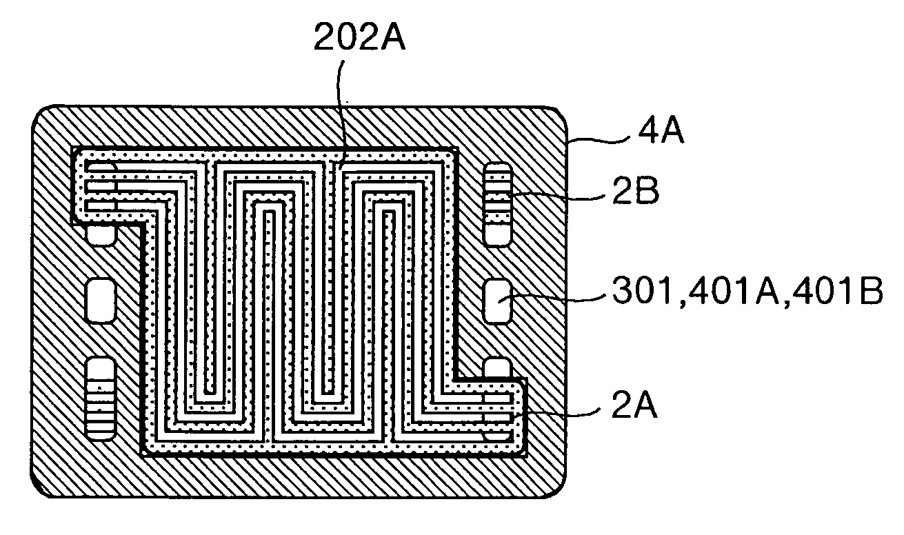
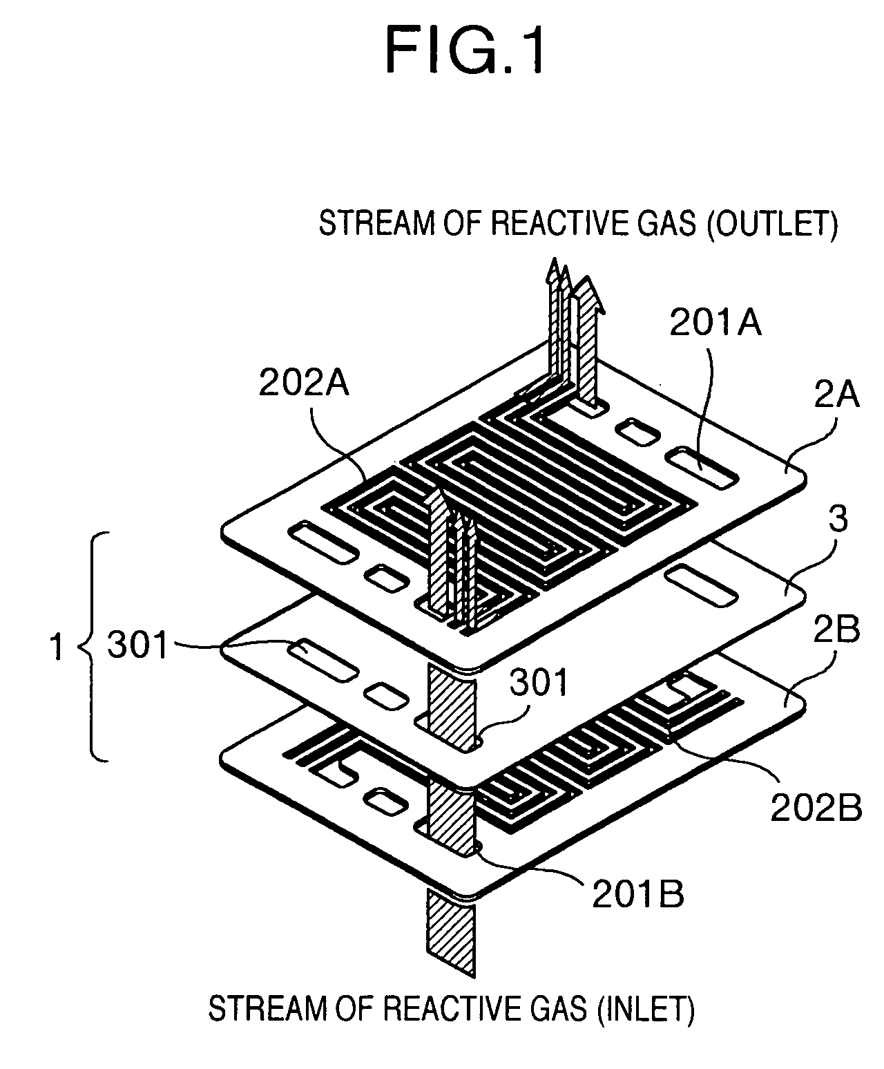
[0049] Explanation will be made of a power generation cell in an embodiment 1 of the present invention with reference to the drawings. Referring to FIG. 1 which shows a basic configuration of a separator according to the present invention, the single separator 1 is composed of covered metal panel 3 formed therein with manifolds 301, and passage boards 2A, 2B superposed over opposite surfaces of the covered metal panel 3 and formed therein with meandering through-channels for distributing reactive gas and cooling medium from the manifolds 301. The passage boards 2A, 2B are formed therein with meandering channels 202 which pierce therethrough and are also formed therein with a plurality of manifolds 201A, 201B as required.

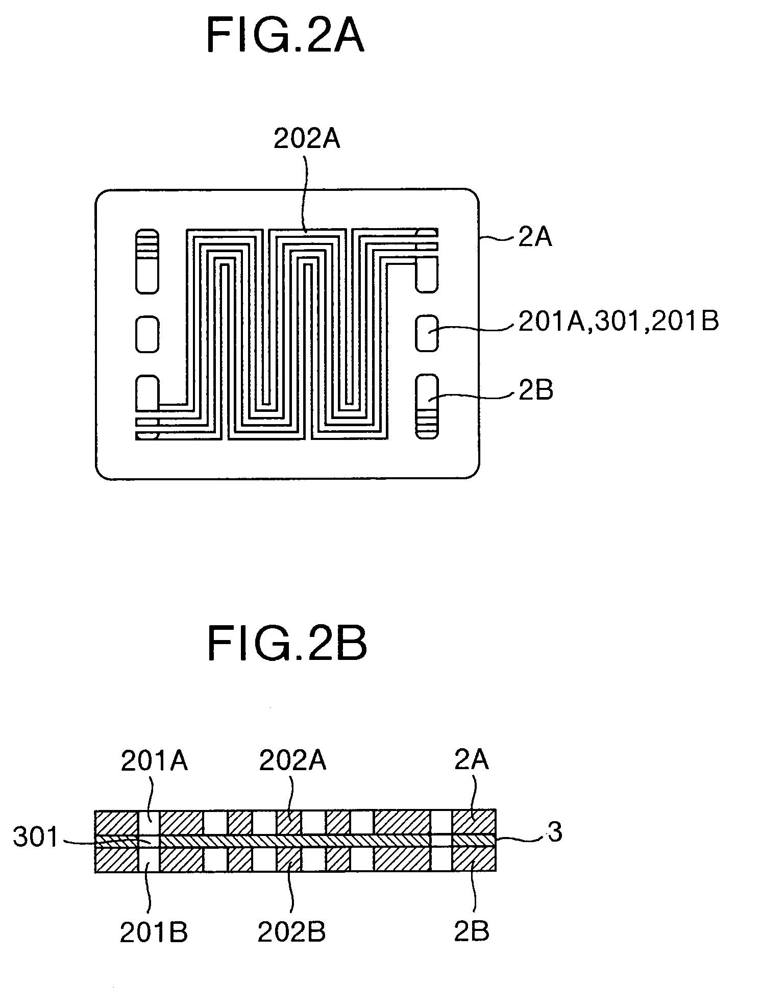
[0050] Referring to FIGS. 2A and 2B which show the covered metal panel 3 and the passage boards 2A, 2B which are superposed with each other, one upon another, interposing therebetween the covered metal panel 3, that is, FIG. 2A is a top plan view and FIG. 2B is a sc...

embodiment 2

[0061] Explanation will be hereinbelow made of an embodiment 2 of the present invention with reference to FIG. 5. In this embodiment, the passage boards 2 are made of conductive porous materials. If the passage boards 2 are made of porous material, the quantity of gas fed to the electrode by way of the passage board can be increased, and accordingly, there can be offered such an advantaged that the power generation voltage and the diffusion limit current can be enhanced. Referring to FIG. 5 which shows the separator 1 using the porous passage boards 2, since the passage boards 2 are made of porous materials, the reactive gas can flow though the porous materials, smoothly. Thus, the single passage board 2 as stated in the embodiment 1 cannot be used.

[0062] In this embodiment, by arranging the gaskets 4 around the passage boards 2, it is possible to restrain occurrence of cross-leakage of reaction gas from the anode to the cathode or from the cathode to the anode, leakage between the...

embodiment 3

[0065] Explanation will be hereinbelow made of an embodiment 3 with reference the accompanying drawings. In this embodiment, the covered metal panel 3 as used in the embodiment 1 or 2 is formed therein with slits 310 in a part corresponding to an electrode (the passage channels part of the passage board 2). Referring to FIG. 7 which shows a separator 1 having the covered metal panel 3 formed therein with the slits 310, the basic configuration of the separator in this embodiment is the same as that in the embodiment 1 shown in FIG. 1, except the covered metal panel 3. The part of the covered metal panel 3 in which the slits 310 are formed is a zone where the passage channels 202 corresponding to the electrode in the passage boards 2A, 2B which are mated with each another are superposed with each other. This configuration is shown in FIG. 8.

[0066] The two passage boards 2A, 2B which are superposed with each other are shown in the upper right part of the figure while the covered metal...


PUM

PropertyMeasurementUnit
depthaaaaaaaaaa
depthaaaaaaaaaa
areaaaaaaaaaaa

Abstract

A fuel cell is provided therein with a metal separator for aiming at preventing corrosion and at reducing a contact resistance. The separator is compose of conductive passage board formed therein with passages, and a metal planar panel, the passage boards and the metal planar panel being superposed with one another. The metal planar panel is formed therein with a plurality of manifolds for passing reactive gas or cooling medium through an adjacent cell while the passage boards are formed therein with a plurality of meandering through channels for distributing the reactive gas or the cooling medium from the manifolds. Further, a part of the meandering through channels is superposed with a part or all parts of the manifolds, and a covering layer for preventing the metal planar panel from being corroded, and for restraining a growth of a nonconductive film is formed over an entire part of the metal planar panel or over at least a part thereof which makes contact with the meandering through channels.

Description

BACKGROUND OF THE INVENTION [0001] The present invention relates to a separator which is one of components in a fuel cell, and also relates to a fuel cell using thereof. [0002] There have been several kinds of fuel cells which are sorted in view of kinds of electrolytes used therein. For example, a phosphate acid fuel cell (PAFC) has a carrier impregnated therein with phosphate, and is adapted to be operated at a temperature in a range from 150 to 220 deg.C. A molten carbonate fuel cell (MCFC) includes a molded electrolyte carrier made of a mixture of lithium carbonate and potassium carbonate, and is adapted to be operated at a temperature in a range from 600 to 700 deg.C. Further, a solid oxide fuel cell uses, as electrolyte, stabilized zirconium having oxygen ion conductivity, and is adapted to be operated at a temperature from 700 to 1,000 deg.C. Any of the above-mentioned fuel cells utilizes hydrogen, reformed gas, hydrocarbon or the like as a fuel, and air or the like as oxidiz...

Claims


Application Information

Patent Timeline
Patent Type & Authority Applications(United States)
IPC IPC(8): H01M8/02H01M2/08H01M8/04H01M8/10H01M8/24
CPCH01M8/0204Y02E60/523H01M8/021H01M8/0234H01M8/0239H01M8/0243H01M8/0263H01M8/0267H01M8/0273H01M8/04029H01M8/04074H01M8/1011H01M8/242H01M2008/1095H01M8/0206H01M8/2483Y02E60/50
Inventor YAMAUCHI, HIROSHIYAMAGA, KENJITAKAHASHI, KO
Owner HITACHI LTD
Why Eureka
Try Eureka