Eureka AIR delivers breakthrough ideas for toughest innovation challenges, trusted by R&D personnel around the world.

Temperature detection method and apparatus for inverter-driven machines

Inactive Publication Date: 2005-10-13
RELIANCE ELECTRIC TECH
View PDF30 Cites 17 Cited by
  • Summary
  • Abstract
  • Description
  • Claims
  • Application Information

AI Technical Summary

Benefits of technology

[0009] In accordance with a first aspect of the technique, a resistance temperature detector suitable for detecting temperatures between windings of an electrical machine is provided. This detector includes a resistive element and a detector insulating system disposed about and completely encasing the resistive element. The resistive element is configured to receive an input signal and to produce an output signal that is a function of temperature. The provided detector insulating system disposed about the resistive element may have a capacitance per unit area approximately equal to or greater than the capacitance per unit area of the winding insulating system.
[0010] In particular, a resistance temperature detector is provided wherein a detector insulating system disposed about a resistive element may have a capacitance per unit area of sufficient magnitude that a voltage stress level experienced by any air voids or low dielectric materials adjacent to the resistive element resulting from voltage applied to the windings during operat

Problems solved by technology

The environments in which conventional resistance temperature detectors are placed are often severe, particularly in high power motors.
The corresponding voltage stress and electric field within these environments may lead to premature failure of resistance temperature detectors.
Particularly, the electric field within the motor may electrically break down small air gaps or other materials or zones of reduced dielectric constant within a resistance temperature detector, causing partial discharge and localized heating within such zones.
If any air voids or low dielectric materials are disposed adjacent to the resistive element of the detector, this localized heating may cause the detector to report inaccurate temperatures or may cause the resistive element to deteriorate, resulting in the failure of the detector.
Moreover, winding insulation systems are being further reduced in thickness, leading to increasing voltage stresses, particularly across temperature detector insulating layers.
Such elevated stresses can similarly lead to failure of the detectors.

Method used


Image

  • Temperature detection method and apparatus for inverter-driven machines
  • Temperature detection method and apparatus for inverter-driven machines
  • Temperature detection method and apparatus for inverter-driven machines

Examples


Embodiment Construction

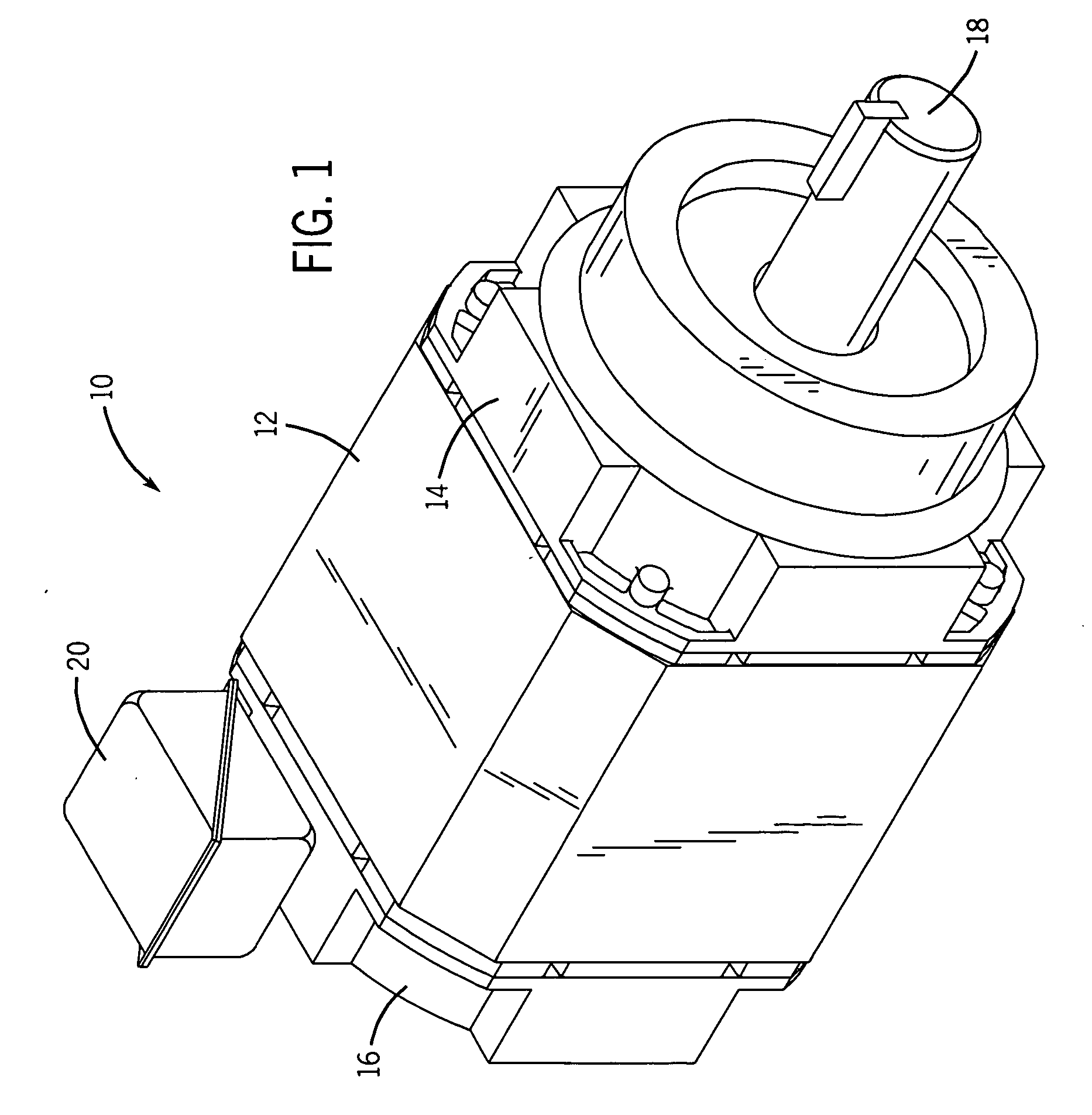
[0022] Turning now to the drawings, and referring first to FIG. 1, an electric motor is shown and designated generally by the reference numeral 10. In the embodiment illustrated in FIG. 1, motor 10 is an induction motor housed in a conventional enclosure. Accordingly, motor 10 includes a frame 12 open at front and rear ends and capped by a front end cap 14 and a rear end cap 16. Frame 12, front end cap 14, and rear end cap 16 form a protective shell, or housing, for a stator and a rotor. Stator windings are electrically interconnected to form groups, and the groups are, in turn, interconnected in a manner generally known in the art. The windings are further coupled to terminal leads (not shown). The terminal leads are used to electrically connect the stator windings to an external power cable (not shown) coupled to a source of electrical power. Energizing the stator windings produces a magnetic field that induces rotation of the rotor and a rotary shaft 18. The electrical connection...


PUM


Abstract

A resistance temperature detector device and system are provided for measuring the temperature adjacent to windings within a stator assembly. The resistance temperature detector comprises a resistive element enclosed within a plurality of insulative layers, including insulation panels and adhesive. These surrounding insulation layers are sufficient to prevent partial discharge within any air gaps or low dielectric materials adjacent to the resistive element when the resistance temperature detector is disposed within a motor. A method for detecting temperatures between windings of an electrical machine is also provided.

Description

BACKGROUND [0001] The present technique relates generally to the field of electric motors and to methods and apparatus for detecting temperatures within an electric motor. More particularly, the technique relates to a novel approach to detecting the temperature adjacent to a winding within an electric motor. [0002] Electric motors, generators, and other similar devices, are produced in a variety of mechanical and electrical configurations. The configuration of these devices may depend upon the intended application, the operating environment, the available power source, or other similar factors. In general, these devices include a rotor surrounded at least partially by a stator. For instance, one common design of electrical motor is the induction motor, which is used in numerous and diverse applications. Induction motors typically employ a stator assembly including a slotted core in which groups of coil windings are installed. By providing alternating current power to certain winding...

Claims


Application Information

Patent Timeline
IPC IPC(8): G01K1/08G01K1/14G01K7/00
CPCG01K1/14G01K1/08
Inventor HUDSON, JEFFREY A.
Owner RELIANCE ELECTRIC TECH
Why Eureka
Eureka Blog
Learn More