An Optical Fiber And Method For Making An Optical Fiber

a technology of optical fibers and optical fibers, applied in the field of optical fibers and methods of making optical fibers, can solve the problems of reducing the mechanical rigidity and support of the cladding, the difficulty of assembling the preform for the hollow core pcf, and the damage to the cladding, so as to reduce the number and/or impact of surface modes, the amount of material used in sealing the crevices or gaps can be sensitively controlled, and the effect of adding additional mechanical rigid

Inactive Publication Date: 2005-10-13
CRYSTAL FIBRE AS
View PDF6 Cites 53 Cited by
  • Summary
  • Abstract
  • Description
  • Claims
  • Application Information

AI Technical Summary

Benefits of technology

[0030] An advantage of embodiments of the present invention is that the amount of material used in sealing the crevices or gaps can be sensitively controlled. For example, the amount of material formed may be the minimum necessary to form a satisfactory seal. For example, if the elements are tightly packed substantially along the entire length of the preform, only a relatively small amount of material would be required to seal the crevices or gaps. In contrast, a relatively thick layer, or complete lining, of material may be formed, which completely covers all the areas of the elements that bound the void. The applicant has demonstrated that a core boundary above a certain thickness may induce a beneficial anti-resonance effect, which can reduce the number and / or impact of surface modes that may be guided by the respective fiber. Another advantage of embodiments of the present invention is that the material may act to bind the elements together, to add additional mechanical rigidity and support to the preform stack during the drawing step. Further, the material typically forms in accord with the contours of the elements around the void, thereby minimizing the degree of deformation that may otherwise occur.
[0031] The material may have substantially the same composition as the elongate elements, or a different composition. For example, either the elongate elements or the material may be doped and the other(s) may be pure. Alternatively, both may be differently doped. The material may be doped to provide certain optical characteristics, for example a specified refractive index, which may be higher or lower than the refractive index of the elements. Alternatively, or in addition, the material may be doped to modify a physical characteristic, for example, softening point, of the material. In some embodiments, the material may be doped to provide it with a lower softening point, in order that the material softens before the elements during fiber drawing. In this way, the material may act like a flux in order to seal the void.

Problems solved by technology

In contrast, it can be more difficult to assemble a preform for a hollow core PCF, since the hollow core defect in a resulting fiber typically needs to have a cross sectional size that is significantly larger than any one cladding hole, in order for the core defect to be large enough to support at least one core-guided mode.
It has, however, been found difficult to heat the stack to a temperature sufficient to fuse the capillaries without the capillaries deforming or even collapsing.
The present inventors have found that a thicker core boundary can lead to deleterious effects, such as becoming a means for supporting unwanted surface modes, which are guided on or near to the surfaces of the core boundary.
These surface modes can become loss paths, due to undesirable coupling of power from core-guided modes to the surface modes.
An additional problem with using a large diameter capillary in a core region is that it can be difficult to match the outer cross sectional shape of the capillary, at the dimensions required in a stack, with the cross sectional shape of the void left by omitting one or more capillaries.
In the former case, accurately forming a capillary 12 with a cross section that is not round can be difficult, particularly if the capillary needs to be drawn down to a different scale after initial formation.
While the unwanted voids can be removed by evacuating them during a fiber drawing step, such evacuation can result in undesirable core boundary deformation, caused by portions of the large diameter capillary and portions of the cladding capillaries, around the unwanted interstitial voids, deforming towards one another as the voids close.
In this event, a resulting PCF structure may acquire different sizes and shapes of hole around the core defect, which can disrupt the band-gap, for example by reducing its bandwidth of operation.

Method used


Image

  • An Optical Fiber And Method For Making An Optical Fiber
  • An Optical Fiber And Method For Making An Optical Fiber
  • An Optical Fiber And Method For Making An Optical Fiber

Examples


Embodiment Construction

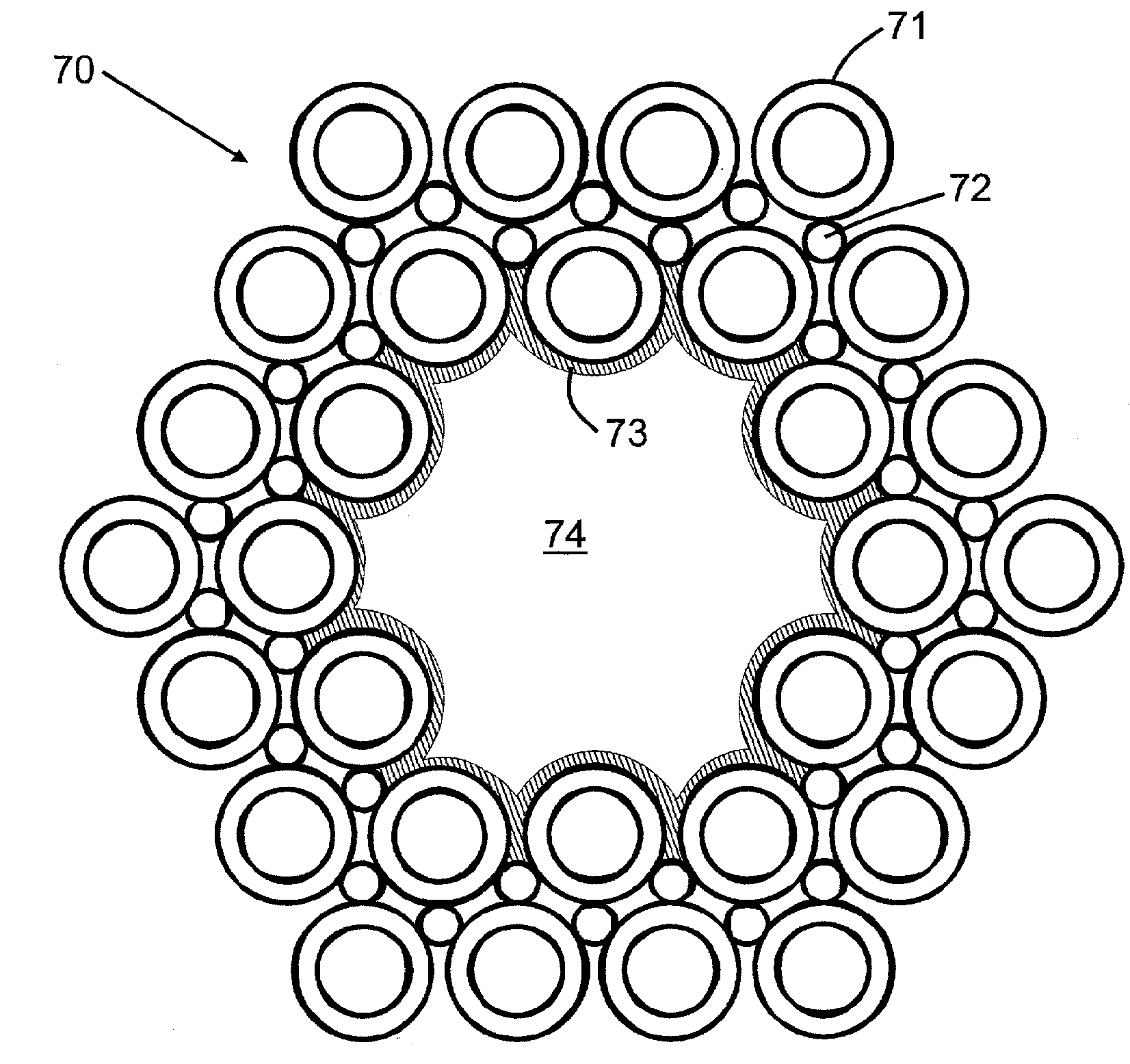
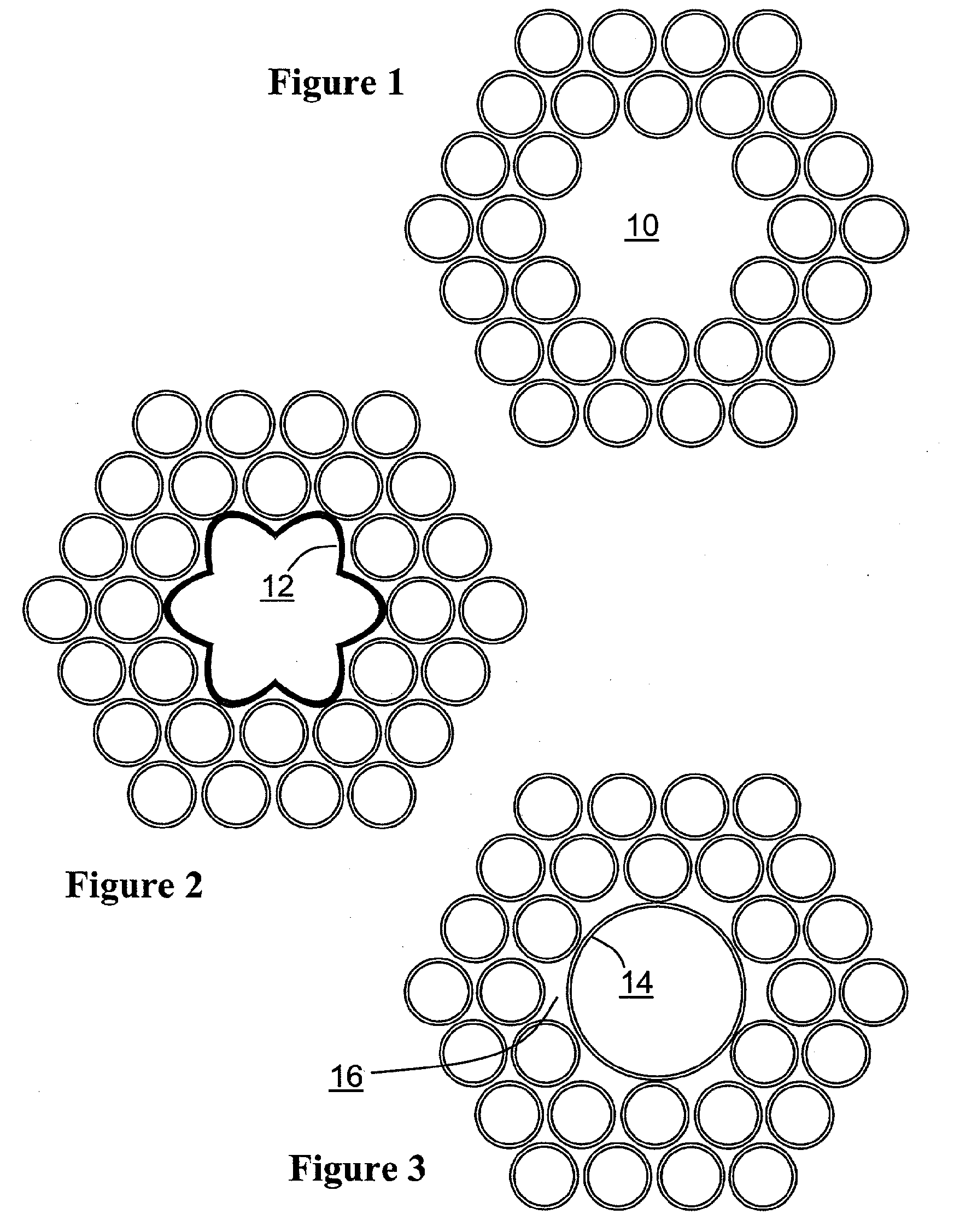
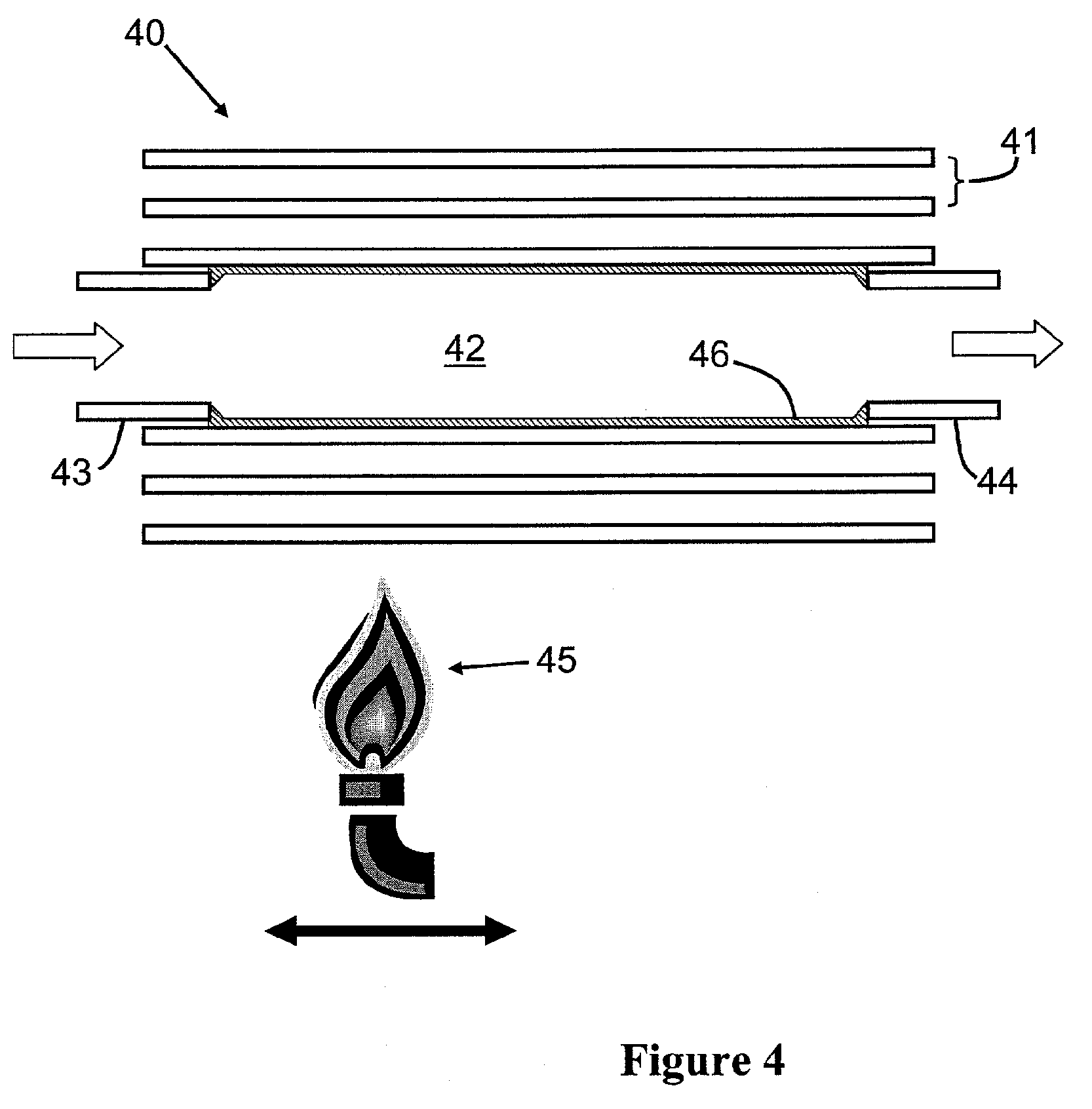
[0042]FIG. 4 illustrates an inner region of a preform stack 40 in longitudinal cross section. The preform stack 40 comprises a plurality of round cross section silica capillaries 41 stacked in a hexagonal close packed arrangement of the kind illustrated in FIG. 1. The capillaries 41—only two layers of which are shown arranged around a core defect region 42—are supported around the core defect at each end of the stack by a short length of large diameter glass capillary tube, 43 and 44. The glass capillary tubes 43, 44 act to support the capillaries 41 around the core defect region 42 and also act as an inlet and an outlet for connection to an MCVD gas supply (not shown). The entire stack is inserted into an over cladding tube (not shown), which is large enough to receive the stack as a sliding fit and small enough that the entire arrangement can be rotated about its longitudinal axis without the capillaries becoming dislocated. Next, the entire over clad stack is mounted on an MCVD l...


PUM

PropertyMeasurementUnit
pressureaaaaaaaaaa
lengthsaaaaaaaaaa
refractive indexaaaaaaaaaa

Abstract

A photonic optical fiber and method of making the optical fiber. The method includes assembling a plurality of elongate elements to define an elongate void; forming within the void a material contacting at least some of the elements while maintaining the elongate void; and drawing a preform, including the assembly of elongate elements, into an optical fiber.

Description

FIELD OF THE INVENTION [0001] The present invention relates to an optical fiber and methods of making optical fibers and particularly, but not exclusively, to photonic crystal fibers and methods of making photonic crystal fibers or the like in which the fibers have one or more elongate holes running along their lengths. BACKGROUND OF THE APPLICATION [0002] Photonic crystal fibers (PCF), or holey fibers as they are sometime referred to, are a relatively new class of optical fibers. Most commonly, these fibers have a core surrounded by a periodic array of elongate holes formed in a matrix material. The array acts to confine light to the core. Since the core, in effect, breaks the periodicity of the array of holes, it is often referred to as a core defect. [0003] In one class of PCF, the core defect is solid and the holes are formed in a matrix material, which is typically made from the same material as the core. The combination of the holes and the matrix material in this kind of fibe...

Claims


Application Information

Patent Timeline
Patent Type & Authority Applications(United States)
IPC IPC(8): C03B37/012C03B37/018C03B37/027G02B6/02
CPCC03B37/0122C03B37/01262C03B37/01807C03B37/02781G02B6/02347C03B2203/16C03B2203/42G02B6/02328C03B2203/14
Inventor MANGAN, BRIAN JOSEPHFARR, LANCE
Owner CRYSTAL FIBRE AS
Why Eureka
Try Eureka