Control device of internal combustion engine

a control device and internal combustion engine technology, applied in the direction of electric control, machines/engines, mechanical equipment, etc., can solve the problems of inability to prevent, inability to strictly control the air-fuel ratio, and inability to adjust the intake air amount, etc., to achieve good precision egr control

Inactive Publication Date: 2005-10-20
TOYOTA JIDOSHA KK
View PDF0 Cites 91 Cited by
  • Summary
  • Abstract
  • Description
  • Claims
  • Application Information

AI Technical Summary

Benefits of technology

[0042] By using the suitable parameter for the injection mode or combustion mode from among these combustion parameters so as to control the fuel injection amount, injection timing, amount of EGR gas, etc., the combustion state of the engine is optimally controlled.
[0043] Further, in particular for control of the EGR, if using as the combustion parameter the time Δt from the start of fuel injection until the crank angle where the maximum value PVmax of the product of the above-mentioned combustion chamber pressure and combustion chamber actual volume occurs, good precision EGR control becomes possible.
[0044] Similarly, for control of the EGR, even if using as the combustion parameter the time Δtc after the start of fuel injection until the value of PVκ calculated based on the combustion chamber pressure P, the combustion chamber volume V determined from the crank angle θ, and the specific heat ratio κ of the combustion gas becomes the minimum value PVκmin or the time Δtc after the start of fuel injection from a fuel injector when the value of PVκ becomes the minimum value PVκmin to when it becomes the maximum value PVκmax, good precision EGR control becomes possible.

Problems solved by technology

However, in a diesel engine, generally the amount of intake air is not adjusted.
Therefore, in a conventional diesel engine, the air-fuel ratio is not strictly controlled as in a gasoline engine.
With open loop control, however, it was impossible to prevent error in the actual fuel injection amount compared with the target fuel injection amount and was difficult to accurately control the combustion state to the targeted state.
Further, in a common rail type high pressure fuel injection system designed to be employed in recent diesel engines for improving the combustion state, since the fuel injection period is short and the fuel injection pressure changes during the injection, there is the problem of a susceptibility to error in the fuel injection amount.
Therefore, in a common rail type high pressure fuel injection system, measures have been adopted such as setting the tolerance of the fuel injectors small so as to improve the fuel injection accuracy, but in practice fuel injectors change in fuel injection characteristics along with the period of use due to wear of the parts etc., so with open loop control, it is difficult to make the fuel injection parameters constantly accurately match with the target values.
In this way, in a diesel engine, error is liable to occur in the fuel injection amount etc., so even if setting target values giving the optimal combustion state, in practice sometimes making the fuel injection amount match with the target value is difficult.
However, EGR gas has a large effect on combustion.
In particular, in a diesel engine, the amount of EGR gas has a large effect on the ignition delay time from the start of fuel injection to when the injected fuel starts to burn.
Therefore, if EGR gas is excessively supplied to the combustion chamber, the engine combustion state will deteriorate and a drop in the engine performance and deterioration of the exhaust gas properties will occur.
On the other hand, if the amount of EGR gas is small, the effect of suppression of the harmful emissions will fall.
However, conventionally the amount of EGR gas has not been controlled precisely.
If precisely controlling the EGR in this way, a sufficient accuracy cannot be obtained with open loop control based on the engine speed and accelerator opening degree like in the past.
Further, for example, it is possible to arrange an air-fuel ratio sensor in the engine exhaust passage and to control the amount of EGR gas based on the exhaust air-fuel ratio detected by the air-fuel ratio sensor, but with an engine like a diesel engine which is operated in a state where the exhaust air-fuel ratio is extremely lean, the detection accuracy of the air-fuel ratio sensor falls, so there is the problem that if controlling the amount of EGR gas based on the exhaust air-fuel ratio detected by the air-fuel ratio sensor, the error becomes large.
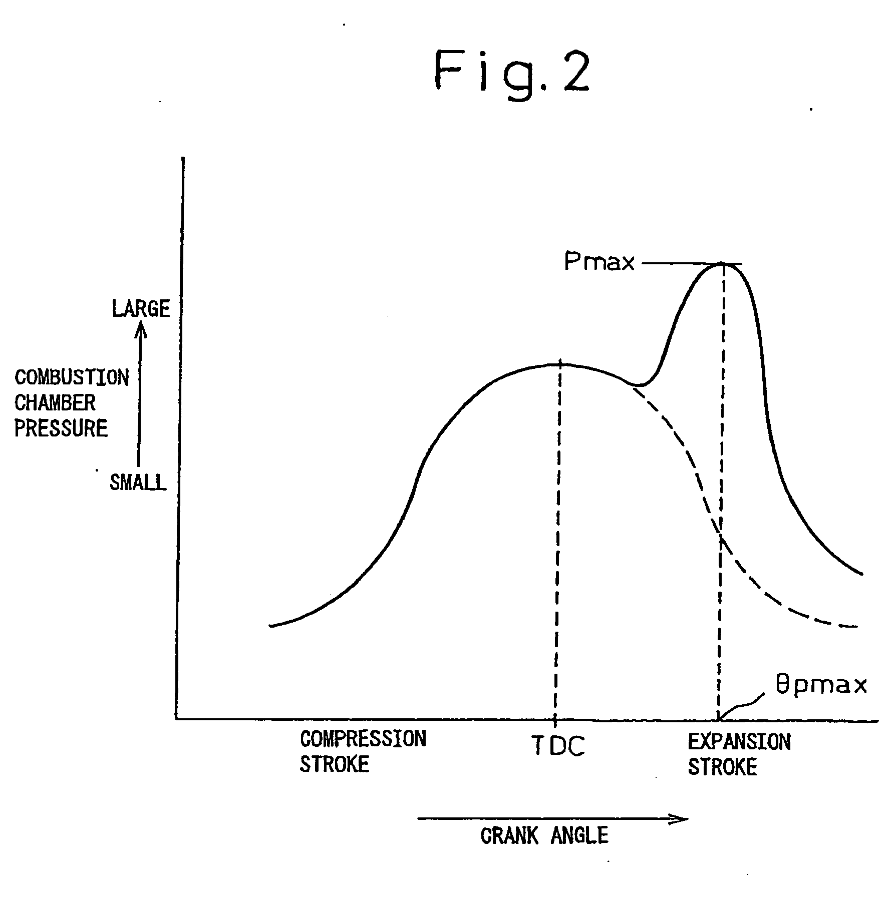
For this reason, since the change in pressure in a combustion chamber greatly differs depending on the injection mode or combustion mode as well, feedback control of the combustion state by just the peak positions or pattern of the heat release rate is not necessarily suitable.
For example, in an in-cylinder fuel injector of a diesel engine, the injection amount, injection timing, and other fuel injection characteristics gradually change along with the period of use resulting in deviation in fuel injection characteristics, but such deviation in fuel injection characteristics is difficult to accurately correct based on the peak positions or pattern of the heat release rate.
Further, when performing pilot injection or main fuel injection or after injection or other multi-fuel injection, optimization of the combustion state requires optimal control of the fuel injection amount and injection timing of the fuel of each, but feedback control of the fuel injection characteristics of a plurality of fuel injections is difficult based on only the peak positions or pattern of the heat release rate.
As explained above, since the system of Japanese unexamined Patent Publication (Kokai) No. 2001-123871 feedback controls the pilot injection amount based on the actually measured combustion noise, it can keep the combustion noise below a target level at all times. However, while the system of Japanese Unexamined Patent Publication (Kokai) No. 2001-123871 keeps the combustion noise below a target value, it does not necessarily always obtain a good combustion state.
Conversely, sometimes it deteriorates the exhaust properties.
That is, to obtain good exhaust properties, it is necessary to suitably control not only the injection amount of the pilot injection, but also the injection timing, but the system of Japanese Unexamined Patent Publication (Kokai) No. 2001-123871 controls only the injection amount of the pilot injection based on the combustion noise and does not control the injection timing based on the actual combustion state.
Therefore, the system of Japanese Unexamined Patent Publication (Kokai) No. 2001-123871 has the problem that while the combustion noise falls, the exhaust properties are not always improved.
Further, the system of Japanese Unexamined Patent Publication (Kokai) No. 2001-123871 deals only with pilot injection and even more so only operation with just one pilot injection, so has the problem that it cannot suitably control the injection amounts and injection timings of the different fuel injections in multi-fuel injection consisting of a plurality of pilot injections or after injection performed after main fuel injection.

Method used


Image

  • Control device of internal combustion engine
  • Control device of internal combustion engine
  • Control device of internal combustion engine

Examples


Embodiment Construction

[0073] Below, embodiments of the present invention will be explained using the attached drawings.

[0074]FIG. 1 is a view of the schematic configuration of an embodiment in the case of applying the fuel injection system of the present invention to a vehicular diesel engine.

[0075] In FIG. 1, 1 indicates an internal combustion engine (in the present embodiment, a four-cylinder four-cycle diesel engine provided with a #1 to #4, that is, four, cylinders being used), while 10a to 10d indicate fuel injectors injecting fuel directly into the combustion chambers of the #1 to #4 cylinders of the engine. The fuel injectors 10a to 10d are connected through fuel passages (high pressure fuel pipes) to a common rail 3. The common rail 3 has the function of storing the pressurized fuel supplied from a high pressure fuel injection pump 5 and distributing the stored high pressure fuel through the high pressure fuel pipes to the fuel injectors 10a to 10d.

[0076] This embodiment is provided with an EG...


PUM


Abstract

Cylinders of a diesel engine 1 are provided with cylinder pressure sensors 29a to 29d for detecting combustion chamber pressures. An electronic control unit (ECU) 20 of the engine selects optimum combustion parameters in accordance with a fuel injection mode of fuel injectors 10a to 10d of the engine and a combustion mode determined by the amount of EGR gas supplied from the EGR valve 35 from among a plurality of types of combustion parameters expressing the combustion state of the engine calculated based on the cylinder pressure sensor output and feedback controls the fuel injection amount and fuel injection timing so that the values of the combustion parameters match target values determined in accordance with the engine operating conditions. Due to this, the engine combustion state is controlled to the optimum state at all times regardless of the fuel injection mode or combustion mode.

Description

TECHNICAL FIELD [0001] The present invention relates to a control system for an internal combustion engine, more particularly relates to a control system for optimizing combustion in a diesel engine. BACKGROUND ART [0002] Due to the recent toughening of exhaust gas controls and demands for reducing noise, there has been a rising demand for optimizing combustion in the combustion chambers of diesel engines as well. To optimize combustion, accurate control of the fuel injection amount, fuel injection timing, injection period, etc. becomes necessary even in diesel engines. [0003] However, in a diesel engine, generally the amount of intake air is not adjusted. The engine load is controlled by the fuel injection amount. Therefore, in a diesel engine, combustion is performed in a lean air-fuel ratio region considerably higher than the stoichiometric air-fuel ratio. Further, the air-fuel ratio changes depending on the load. Therefore, in a conventional diesel engine, the air-fuel ratio is ...

Claims


Application Information

Patent Timeline
Patent Type & Authority Applications(United States)
IPC IPC(8): F02B3/06F02D21/08F02D35/02F02D41/00F02D41/30F02D41/38F02D41/40
CPCF02B3/06F02D35/023F02D35/028F02D41/0052F02D41/3035Y02T10/47F02D41/38F02D41/3809F02D41/402Y02T10/44F02D41/3064Y02T10/12Y02T10/40
Inventor KOBAYASHI, NOBUKISASAKI, SHIZUOAOYAMA, TAROYOSHIZAKI, KOUJIMURATA, HIROKIHASHIMOTO, YOSHIKIINAGAKI, KAZUHISANAKAKITA, KIYOMINAKAHARA, SHOJIHOTTA, YOSHIHIRO
Owner TOYOTA JIDOSHA KK
Why Eureka
Try Eureka