Touch sensor

Active Publication Date: 2005-10-20
ASA ELECTRONICS IND
View PDF15 Cites 5 Cited by
  • Summary
  • Abstract
  • Description
  • Claims
  • Application Information

AI Technical Summary

Benefits of technology

[0034] According to the touch sensor of the invention, in order to set a reference height of the cutting edge from the working table surface, the anvil contacting with the cutting edge is subject to a parallel movement by means of the parallel link mechanism of the cantilever beams of the parallel plate springs made of polyimide thin plates. Furthermore, the movable portion of the parallel plate springs is made of aluminum alloy thin plates and a tube material with a small diameter, so that its weight is decreased. Thus, it is made possible to set the reference height using a contact load substantially of 0.3 gf or less, so that load is hardly applied to the edge tool.
[0035] With the Hall IC detecting the movement of the magnet caused by the parallel movement of the anvil, it is enabled to detect a displacement at a reproduction precision of ±0.5 μm or less to renew the default position setting the cutting edge. Further, the parallel plate spring has an empty skeleton through which space the supporting block at the fixed end of the cantilever beam is penetrated and constructed, and thus allowing a compact package of the total touch sensor. The movable portion of the parallel plate spring has its self-weight supported by a cantilever elastic wire material and abuts with the bush fixed inside the housing, which allows a compact construction as well as the movable portion of the parallel plate spring to be held stably.
[0036] Furthermore, since the elastically displaced position of the Hall IC supporting member is normally held by the adjusting rod, it is made possible to fine-adjust the relative position between the Hall IC and the magnet to a position indicating the optimal sensitivity, controlling the screw part of the adjusting rod renders. The anvil is freely detachable from the pipe, so that it can be easily replaced when abrasion or deformation occurs. Such a touch sensor can always be installed to a predetermined position on the working table by means of the knock hole drilled on the pedestal, it is made possible for an appropriate clamp to be engaged with and easily bolted to the extended part over-hanged to the exterior of the housing.
[0037] Further, it is possible to prevent the parallel plate springs from deforming excessively to a level exceeding an elastic limit, because the lock-washer fixed untidily to the anvil abuts with the flanged boss fixed to the top surface of the housing so as to limit the anvil movement, and the signal light enables the operation of the Hall IC visible. Moreover, no degradation due to abrasion will occur, because the magnet of the movable portion and the Hall IC of the detecting part are not in contact to each other, and since joints of the parallel link are the plate springs, there is no friction, i.e. no deterioration due to friction.

Problems solved by technology

The revolution speed of the drill reaches hundreds of thousands per minute, causing abrasion to occur at the cutting edge.
On one band, processing a diameter of 0.1 mm or less in the order of 0.01 mm using a diamond drill requires a touch sensor with a very light contact pressure, because activating a touch sensor with a contact load as described above may cause the drill itself to bend at a buckle, resulting in unstable position setting of the drill tip, thereby damaging reproducibility.
But it has a disadvantage that it is difficult to respond to variations in the cutting edge form, because the method has so many adjusting parts for making adjustments, which depend on the characteristics of the electronic circuit, such as adjustments of reproducibility, neutral zone, light amount, and temperature change, so that it is inconvenient for handling and vulnerable to dust.

Method used


Image

  • Touch sensor
  • Touch sensor
  • Touch sensor

Examples


Embodiment Construction

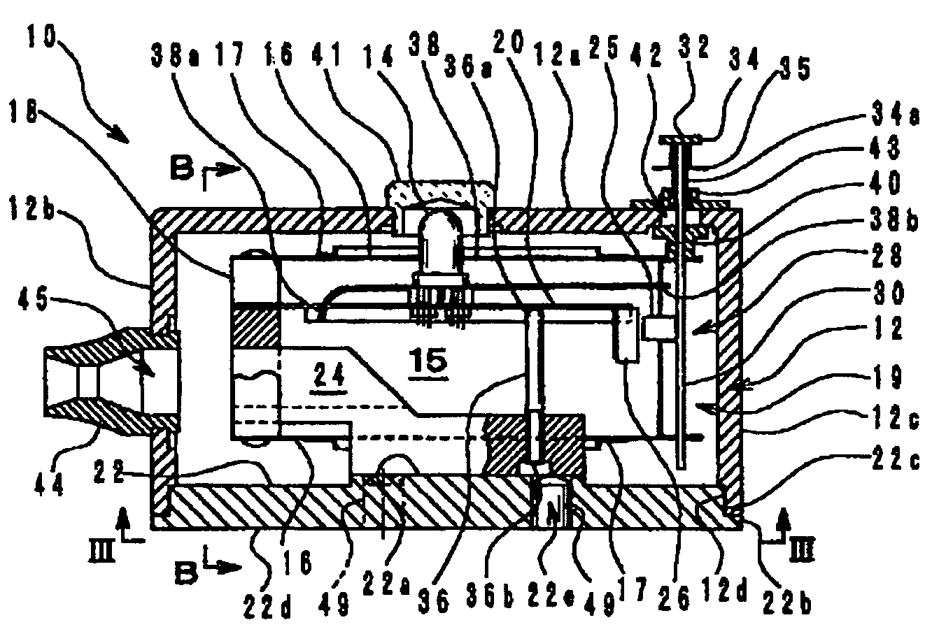
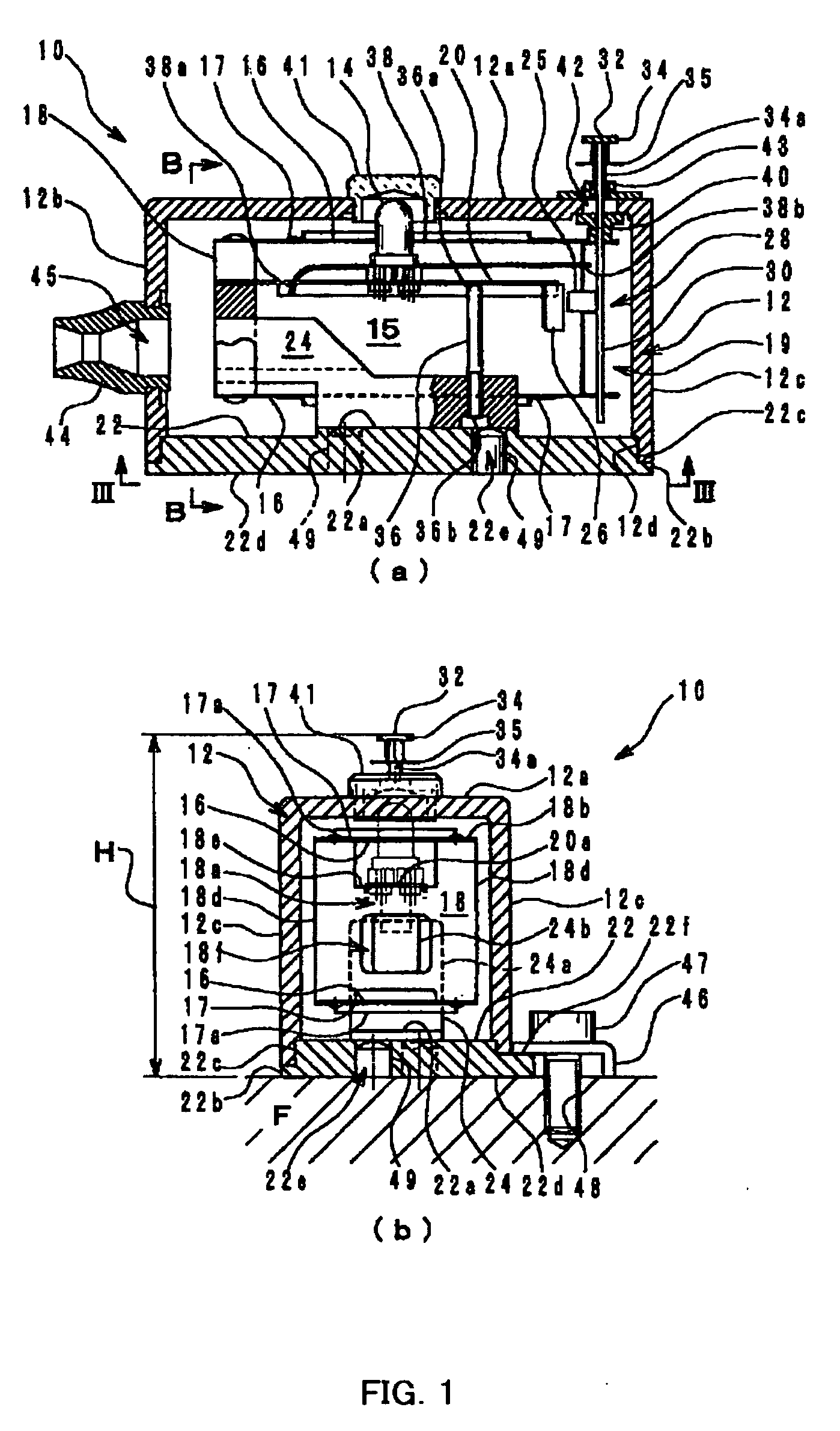
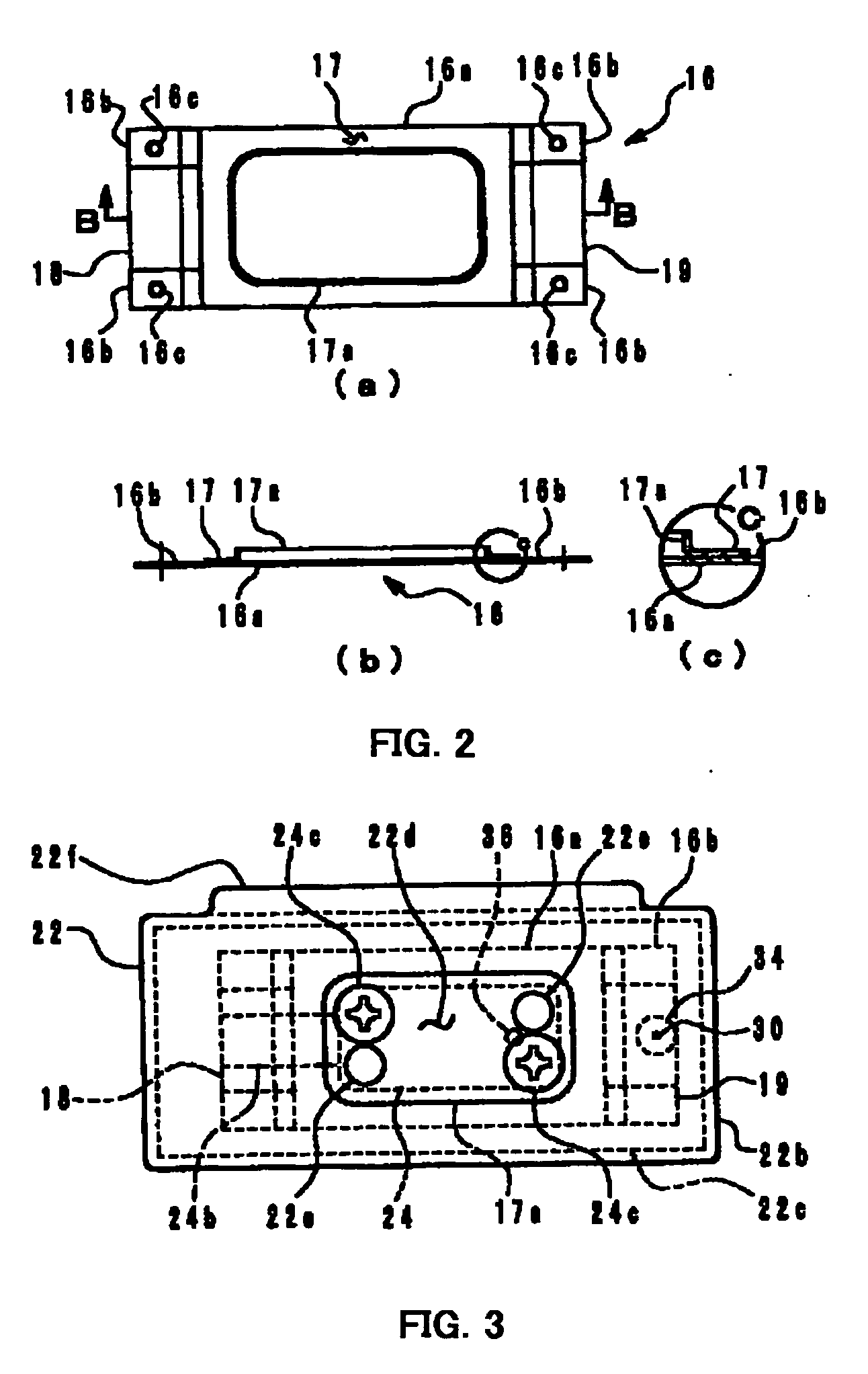
[0046] A preferred embodiment of a touch sensor according to the invention will be now described in detail hereinafter based on the drawings. FIG. 1 shows an embodiment of a touch sensor 10 according to the invention, (a) a side cross-sectional view and (b) a cross-sectional view along line B-B of (a). FIG. 2 is a plan view to illustrate one of two parallel plate springs 16 of the same shape which are constructed mirror-symmetrically opposed to each other having a same geometry, (b) a cross-sectional view along line B-B of (a), and (c) an expanded view of the part of (b) circulated with a sigh c. FIG. 3 is a bottom view along line III-III of FIG. 1(a). FIG. 4 is a perspective view of FIG. 1, parts thereof being disassembled. FIG. 5 is an operational illustration of the touch sensor 10 of FIG. 1, a housing 12 and a signal light 14 being removed. Note that plate thicknesses are all exaggeratedly illustrated in the drawings.

[0047] In FIG. 1, a cantilever mechanism 15 which is a major ...


PUM


Abstract

A touch sensor using a Hall IC is provided. To this end, in a cantilever mechanism 15 of a parallel link by two plate springs 16, a coupling member 18 on the fixed side is fixed to a supporting block 24 which penetrates through the center of a plate spring 16 on a lower side and uprightly provided on a pedestal 22. A movable portion 28 on the free end side is a lightweight coupling member 19 provided by bend-processing an aluminum thin plate, to which a rare-earth magnet 25 is adhered. An elastic part 20a of a Hall IC supporting member 20 is fixed to the coupling member 18 on the fixed side, and a rigid part 20b with a rib 17a is supported by an adjusting rod 36 to fine-adjust relative position of a Hall IC 26 provided on the free end with respect to the magnet 25. Elastic wire materials 38s are fixed to the Hall IC supporting members 20s which hold at a free end 38b the self-weight of the movable portion 28, and abutted with a lower surface 40a of a bush on the inner surface of a housing 12, so that the movable portion 28 is stabilized in its position. A light load of 0.6 gf or less activates an anvil 34, and the Hall IC 26 detects a minute displacement of 0.1 mm or less of the magnet 25, in order to light up a signal light 14.

Description

FIELD OF THE INVENTION [0001] The present invention relates to a touch sensor aiming to correct an error of process dimension due to abrasion of an edge tool by setting a reference position for checking the machining position while the cutting edge of the edge tool such as a bite and drill in an automated computer-controlled machine tool such as a machining center and a jig drilling machine advances. More specifically, the invention relates to a construction of a mechanism that enables it to detect a minute displacement (in microns or sub-microns) with a minute measuring pressure. BACKGROUND ART [0002] In recent years, IC integration level has increased dramatically. This requires further minute precision hole processing, for example, accurately depth-processing 2-4 layers out of 5-6 layers of printed boards in the order of micro-meter, using a drill made of an ultra-hard material such as diamond having a diameter in the order of 0.1 mm or less. The revolution speed of the drill rea...

Claims


Application Information

Patent Timeline
IPC IPC(8): B23Q17/22G01V9/00G01B7/00H03K17/97
CPCH03K17/97
Inventor ASA, YUKIHIRO
Owner ASA ELECTRONICS IND
Why Eureka
Try Eureka